Introdução
Follow this guide to replace a broken or drifting joystick (aka thumbstick or analog stick) for the Xbox Series X/S wireless controller. If you experience persistent stick drift, you can't fix it by cleaning your controller—it's likely a worn out joystick module.
This repair requires intermediate soldering skills. Desoldering the joystick module is difficult, but can be done with some patience.
If you have a hot air station, you can use it to desolder all the contacts simultaneously to extract the joystick. However, this guide shows you how to cut apart the joystick module so you can desolder the pieces individually with a soldering iron. The procedure will destroy the existing joystick module.
Replace the drifting joystick with a TMR joystick module to fix stick wear and drift permanently.
Ferramentas
-
-
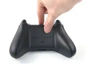
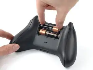
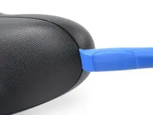
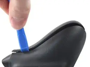
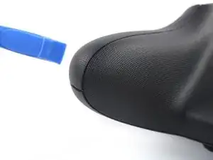
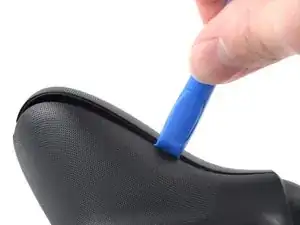
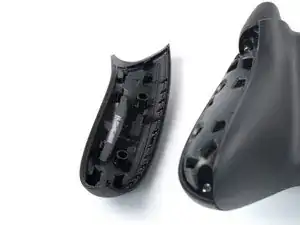
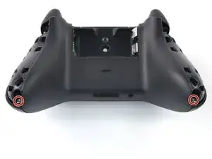
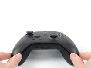
Insert an opening tool between the left handle cover and the bottom inner edge of the back housing.
-
-
-
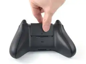
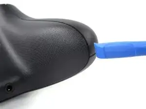
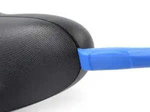
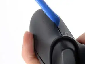
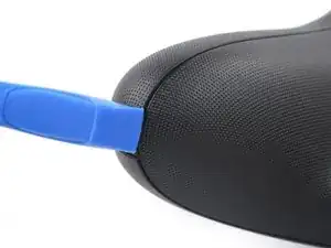
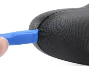
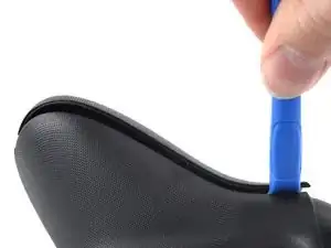
Slide the opening tool along the inner edge of the left handle cover and pry intermittently to release the plastic clips.
-
-
-
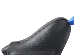
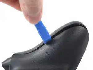
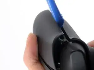
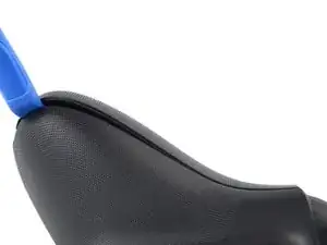
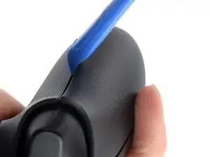
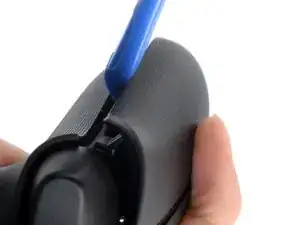
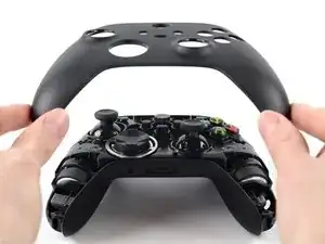
Pry up the middle inner edge of the handle cover with the opening tool to release the remaining clips.
-
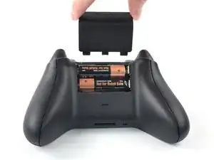
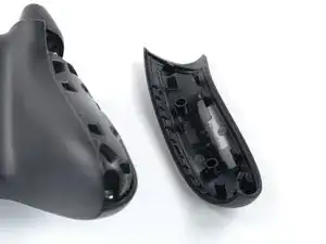
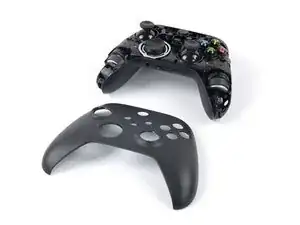
Remove the left handle cover.
-
-
-
Insert an opening tool between the right handle cover and the bottom inner edge of the back housing.
-
-
-
Slide the opening tool along the inner edge of the right handle cover and pry intermittently to release the plastic clips.
-
-
-
Pry up the middle inner edge of the handle cover with the opening tool to release the remaining clips.
-
Remove the right handle cover.
-
-
-
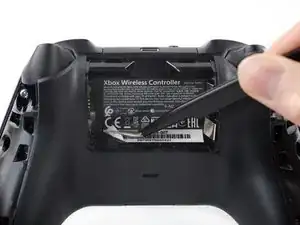
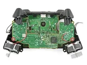
Use a T8R Torx Security driver to remove the five 9.3 mm-long screws securing the top housing, three near the top and two at the bottom.
-
-
-
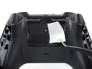
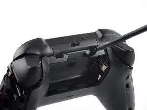
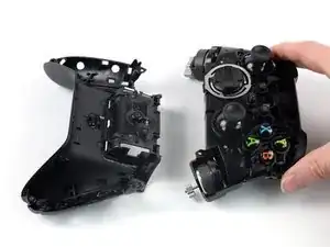
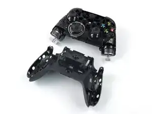
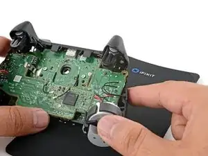
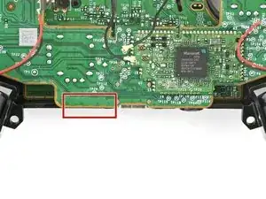
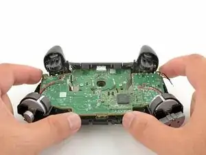
Insert the flat end of a spudger into the rectangular gap between the midframe assembly and back housing, nearest the left bumper.
-
Twist the spudger to partially release the midframe assembly.
-
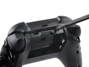
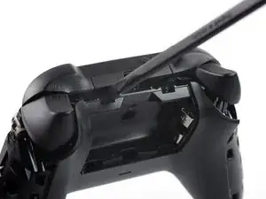
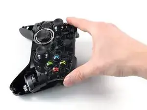
Repeat this prying procedure on the gap near the right bumper to completely release the midframe assembly.
-
-
-
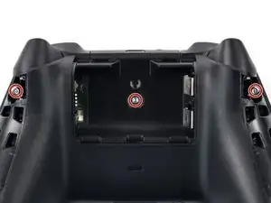
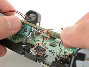
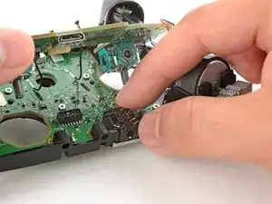
Slide one arm of a pair of tweezers under the antenna coaxial cable connector, as close to the metal head as possible.
-
Lift the connector straight up to disconnect it.
-
Repeat the procedure for the second antenna cable.
-
-
-
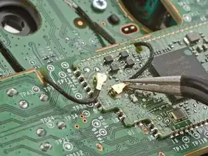
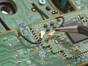
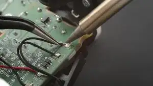
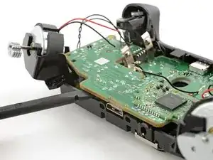
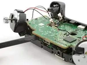
Use your soldering iron to heat up one of the motor wire solder pads.
-
Once the solder is melted, use tweezers to lift the wire away from the pad.
-
-
-
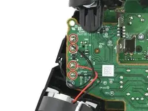
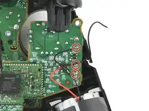
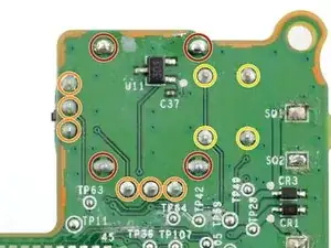
Insert the flat end of a spudger between the daughterboard and the bottom edge of the frame at the location marked on the image.
-
Twist the spudger to push up the daughterboard and disconnect the socket.
-
-
-
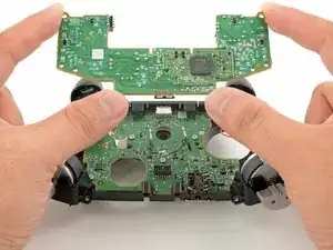
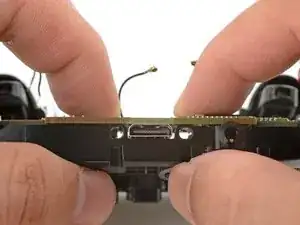
Line up the daughterboard socket to the main board socket.
-
Check that the headphone jack isn't out of position.
-
Check that the antenna cables aren't trapped between the two boards.
-
Use your fingers to gently squeeze the boards together to reconnect the socket.
-
-
-
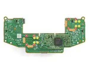
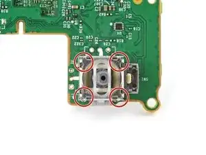
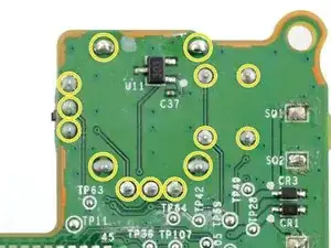
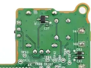
Four frame anchor joints
-
Six joints connecting the two potentiometers
-
Four joystick push-button joints
-
-
-
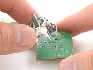
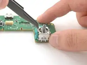
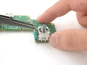
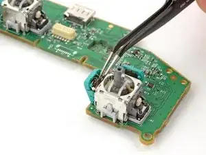
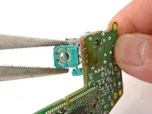
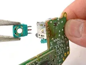
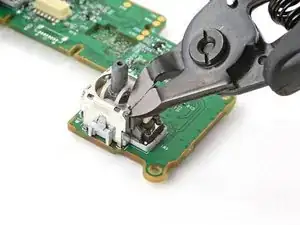
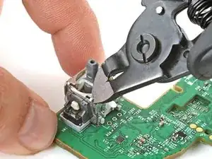
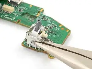
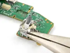
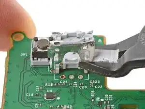
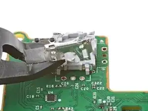
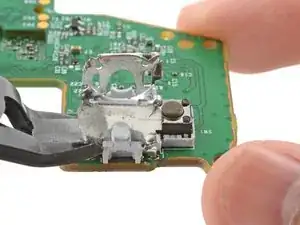
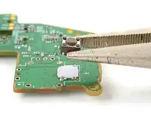
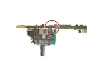
Insert the tips of a pair of angled tweezers between the top edge of a potentiometer and the joystick frame.
-
Pivot the tweezers down to bend the top edge of the potentiometer away from the joystick frame.
-
Repeat the procedure with the second potentiometer.
-
-
-
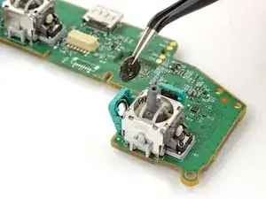
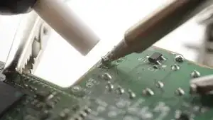
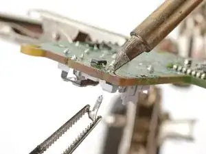
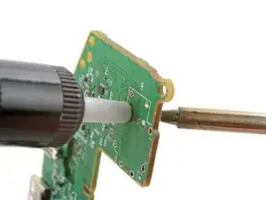
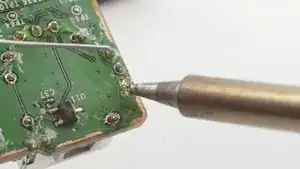
Set your soldering iron to 375 °C (707 °F) and press the tip against a joint to heat it.
-
Once the joint's molten, use a desoldering pump to suck away the solder.
-
Repeat the heating and sucking procedure a few times on the same joint to remove as much solder as possible.
-
-
-
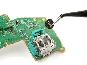
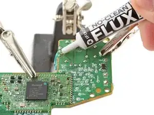
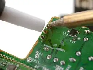
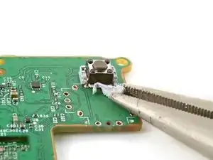
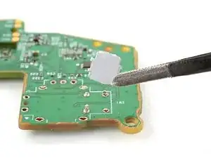
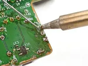
Apply flux to the solder joint.
-
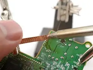
Lay a piece of clean solder wick over the solder joint.
-
Press the tip of your soldering iron over the wick so that the residual solder melts and transfers onto the wick.
-
Repeat the process with the remaining two solder joints.
-
-
-
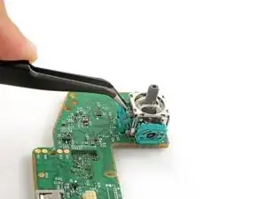
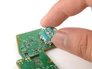
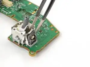
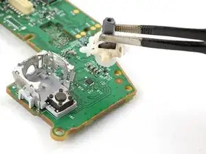
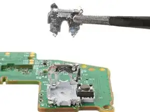
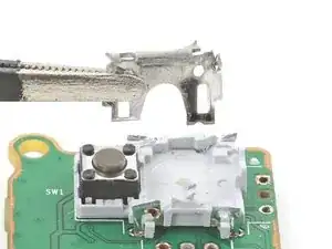
Remove the plastic joystick components from the center of the frame.
-
Remove any loose frame pieces.
-
-
-
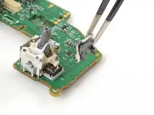
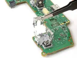
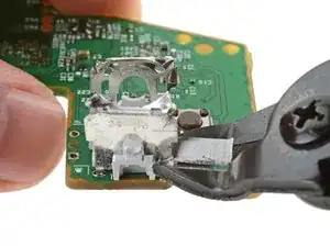
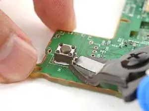
Use flush cutters to cut both legs for one of the frame walls.
-
Remove the loose frame wall.
-
-
-
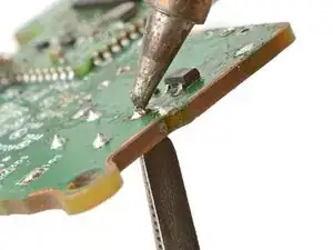
Secure the motherboard so that the solder joints face upward.
-
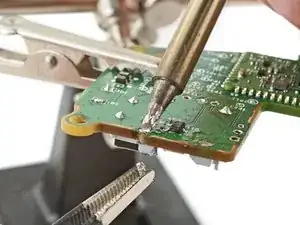
Use your soldering iron to heat a solder joint securing one of the frame anchors.
-
Once the solder is melted, use tweezers to grab and pull the frame anchor out of its through-hole.
-
-
-
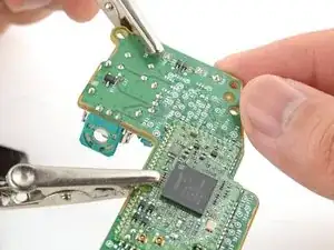
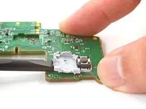
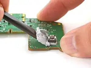
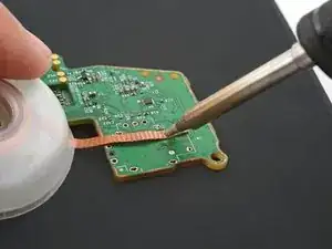
Slide the flat end of a spudger under the joystick module's plastic base.
-
Slowly pry up the base to bend and break it away from the motherboard.
-
Remove the plastic base.
-
-
-
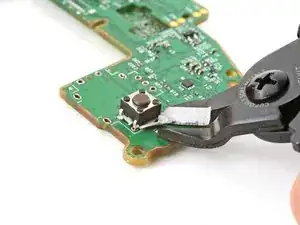
Use flush cutters and pliers to break and remove the plastic base remnants from the push-button.
-
-
-
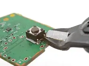
Use flush cutters to cut the four push-button pins along the bottom edge of the button, securing it to the motherboard.
-
-
-
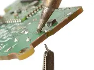
Secure the motherboard so that the solder joints face upward.
-
Use your soldering iron to heat a solder joint securing one of the push-button pins.
-
Once the solder is melted, use tweezers to grab and pull the pin out of its through-hole.
-
Repeat the procedure to remove the remaining three push-button pins.
-
-
-
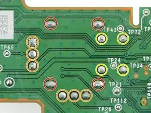
Secure the motherboard so you can access both sides of it.
-
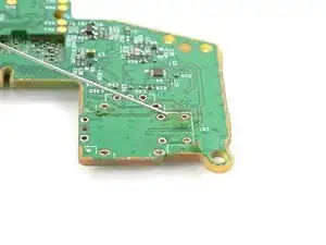
Use the soldering iron to heat one side of a through-hole.
-
Use a desoldering pump on the opposite side of the through-hole to suck up any remaining solder.
-
If needed, use solder wick to remove any residual solder.
-
Repeat this for all through-holes and both sides of the motherboard.
-
-
-
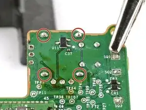
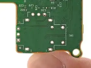
Visually inspect each through-hole and make sure they're not blocked by residual solder. If some holes look blocked, repeat the previous step to clear the blockage.
-
-
-
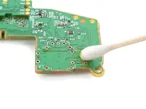
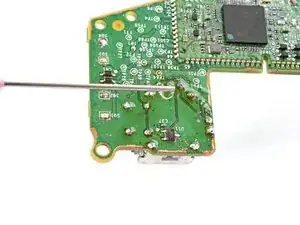
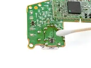
Apply a few drops of high concentration (>90%) isopropyl alcohol to the top side of the motherboard, where the new joystick module will sit.
-
Use a cotton swab or a soft brush and cloth to wipe away the flux residue.
-
-
-
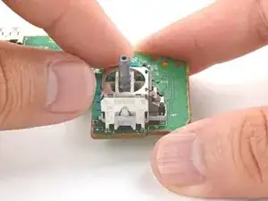
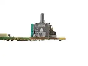
Place the replacement joystick module onto the motherboard.
-
Gently press the joystick onto the board so that the joystick sits flush with the board surface.
-
-
-
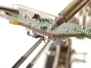
Flip the motherboard over and secure it so that you can solder the joystick module pins.
-
Apply flux to the first few solder pads that you're going to solder.
-
-
-
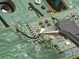
Make sure the joystick module hasn't moved away from the motherboard during the soldering process. Reheat the soldered pin and reposition the module as needed.
-
Solder the remaining pins (14 total) to the motherboard. Apply flux as you solder to help create good bonds.
-
-
-
Visually inspect your work:
-
Make sure each solder joint looks well-formed.
-
Make sure no solder joints are shorting each other.
-
-
-
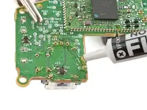
Apply a few drops of high concentration (>90%) isopropyl alcohol to the motherboard wherever you can see flux residue.
-
Use a cotton swab or a soft brush and cloth to wipe away the flux residue.
-
Congratulations! You've replaced the controller's joystick and, in the process, leveled up your soldering skills.
To reassemble the controller, go to this step and follow the instructions in reverse order.
You'll need to run the thumbstick recalibration tool to calibrate the new joystick:
- On an Xbox, press the Xbox button on the controller, then navigate to Settings → Devices & connections → Controllers & headsets.
- On a PC, download the Xbox Accessories app and look for the recalibration option.
Take your e-waste to an R2 or e-Stewards certified recycler.
Repair didn’t go as planned? Try some basic troubleshooting, or ask our Answers community for help.

10 comentários
Happy to report this worked perfectly fine for me, even though my soldering skills are quite bad. Un-Soldering the old parts was quite a tidious task, but going slowly and steady finally made it work. Overall i would say it took me around 4 hours to complete (3,5h of that were for the soldering part ^^).
After reconfiguring the thumbsticks within the xbox internal settings app, everything works perfectly.
OMG, de-soldering the old joysticks was hard, mostly because of big thermal mass of the GND pins. What helped me, was to use a big soldering tip (chisel tip) to remove old pins one by one (when, as per the instruction I pretty much cut old parts into pieces which made removing individual pins separately possible), and then I used fine tip putting it into each THT hole and sucked solder from the other side. Great guide!
I just completed it and the guide was excellent. I used a hot air station i got for Christmas and it made it so god damm easier BUT make sure you add some kapton tape on the bottom of your new sticks so you dont melt the plastic, i did it on one of the sticks and now its kinda weird.
Also be very careful with the antennas, i think i bumped one of the connectors with my iron or something and now it wired only, but thats ok since its only used at my desk or connected to my switch thru a cable
Overall this is a very good guide for a very hard job, but if i had to reccomend some changes i would add the tip suggestions from @lukasziwas53885 since those were great tips from him