Introdução
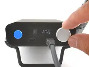
Follow this guide to replace a broken or drifting joystick (aka thumbstick or analog stick) for the PlayStation DualSense v2 controller. If you experience persistent stick drift, it's likely due to a worn out joystick module.
This repair requires intermediate soldering skills. Desoldering the joystick module is difficult, but can be done with some patience.
This guide shows you how to cut apart the joystick module so you can desolder the pieces individually with a soldering iron. The procedure will destroy the existing joystick module. If you have a hot air station, you'll have an easier time desoldering the joysticks.
Consider replacing the drifting joystick with a TMR joystick module to fix stick wear and drift permanently.
Ferramentas
-
-
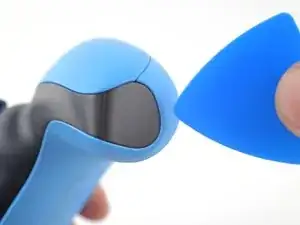
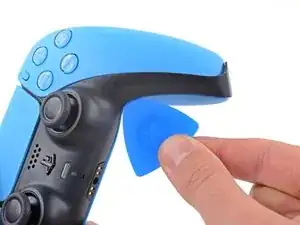
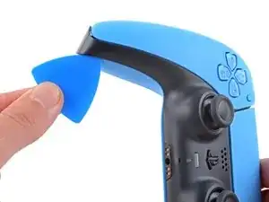
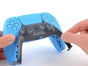
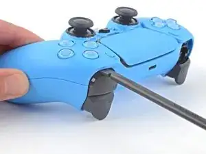
Insert an opening pick underneath the middle trim at the bottom-right corner of the controller to release the clips securing it to the case.
-
-
-
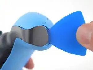
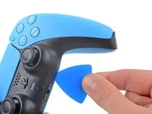
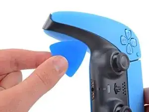
Slide the opening pick along the lower-right edge of the middle trim to release the clips securing it to the case.
-
-
-
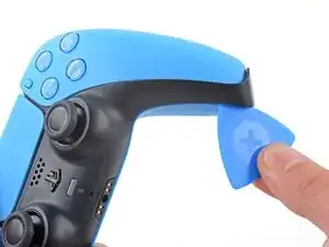
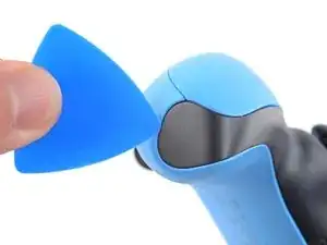
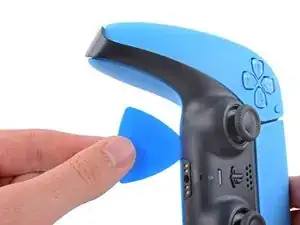
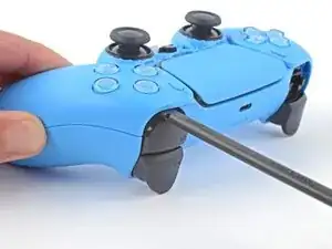
Insert an opening pick underneath the middle trim at the bottom-left corner of the controller to release the clips securing it to the case.
-
-
-
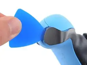
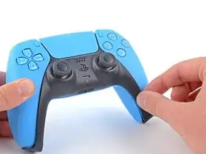
Slide the opening pick along the lower-left edge of the middle trim to release the clips securing it to the case.
-
-
-
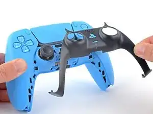
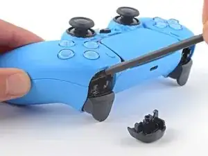
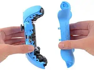
Use your fingers to lift up the bottom edge of the middle trim to release the remaining clips.
-
Lift the middle trim over the joysticks to remove it.
-
-
-
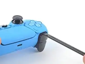
Insert the flat end of a spudger into the gap above the L1 button.
-
Pry the spudger upward to remove the L1 button.
-
-
-
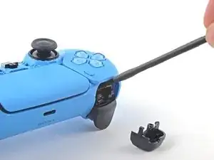
Insert the flat end of a spudger into the gap above the R1 button.
-
Pry the spudger upward to remove the R1 button.
-
-
-
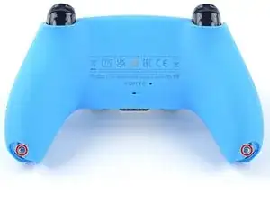
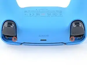
Use a Phillips screwdriver to remove the two 6.5 mm screws securing the bottom corners of the lower case.
-
-
-
Use the pointed edge of a spudger to unclip the two clips on either side of the headset jack.
-
-
-
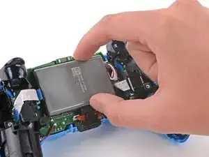
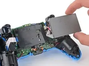
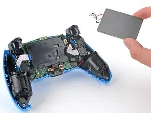
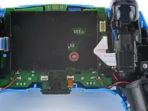
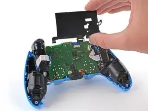
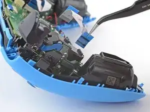
Lift the battery out of its bracket and reposition it to the right for better access to the battery connector.
-
-
-
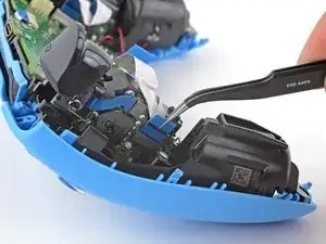
Use the pointed end of a spudger to remove the lower microphone from its bracket next to the battery.
-
-
-
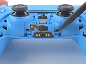
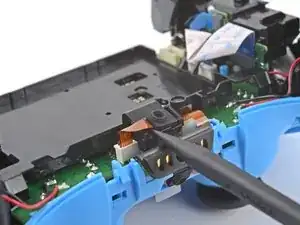
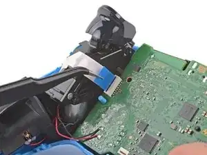
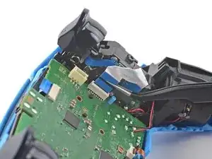
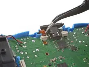
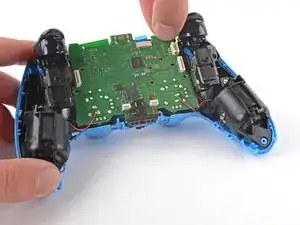
Grip the right trigger assembly cable with a pair of tweezers or your fingers and disconnect it from the motherboard.
-
Don't completely remove the ribbon cable yet.
-
-
-
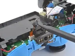
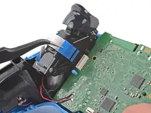
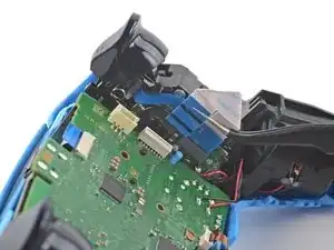
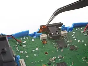
Grip the right trigger assembly cable with a pair of tweezers or your fingers, and disconnect it from the trigger assembly.
-
-
-
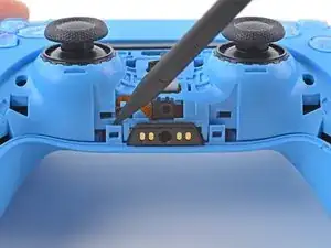
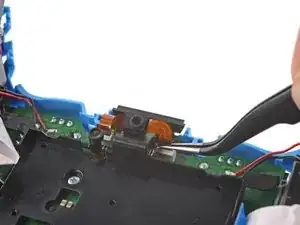
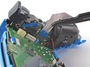
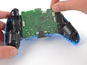
Grip the left trigger assembly cable with a pair of tweezers or your fingers to disconnect it from the motherboard.
-
Don't completely remove the ribbon cable yet.
-
-
-
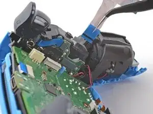
Grip the left trigger assembly cable with a pair of tweezers or your fingers to disconnect it from the trigger assembly.
-
-
-
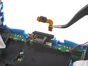
Use a pair of tweezers or your fingers to disconnect the upper microphone from the motherboard.
-
-
-
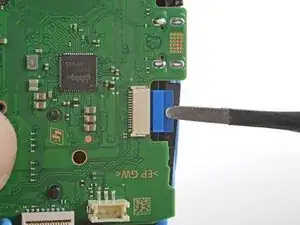
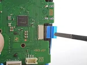
Use a pair of tweezers or your fingers to disconnect the touchpad cable from the motherboard.
-
-
-
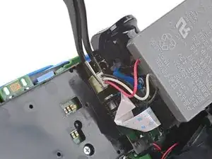
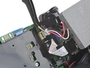
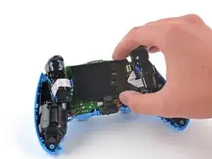
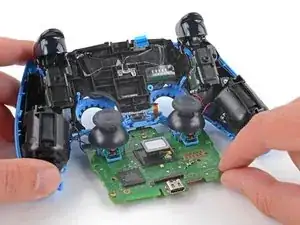
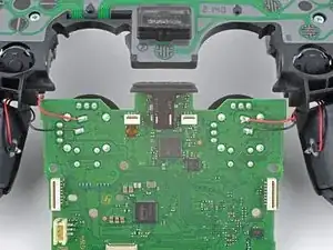
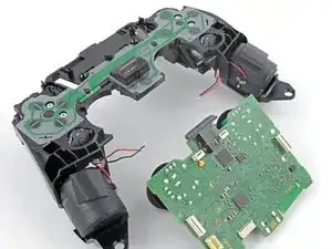
Flip the motherboard and midframe over to access the red and black vibration motor wires.
-
Use a soldering iron to disconnect the vibration motor wires from the motherboard.
-
-
-
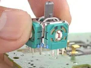
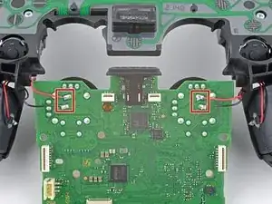
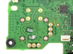
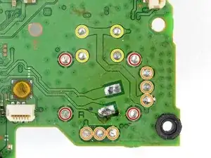
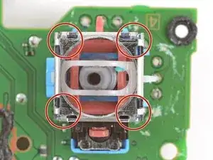
Four anchor joints
-
Six joints connecting the two potentiometers
-
Four joystick push-button joints
-
-
-
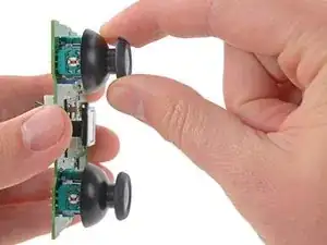
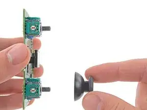
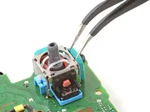
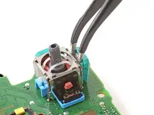
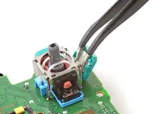
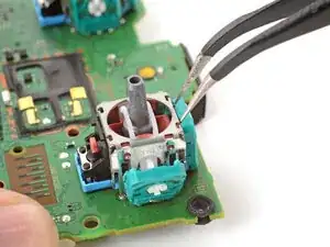
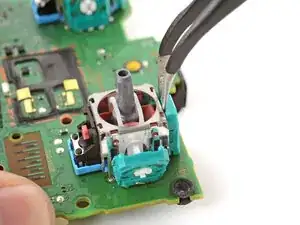
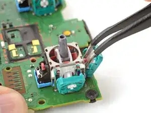
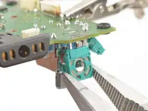
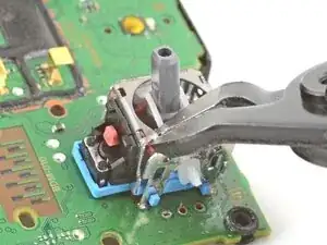
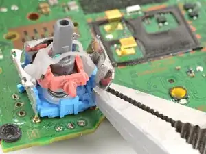
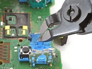
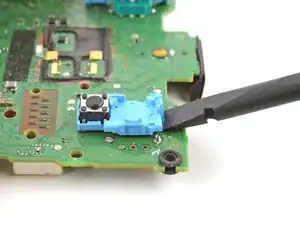
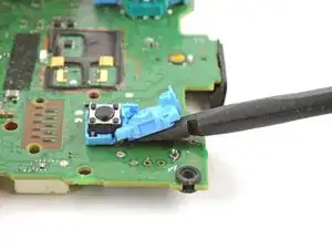
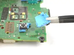
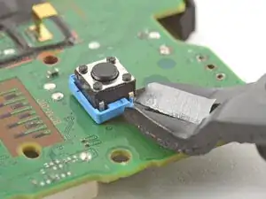
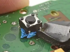
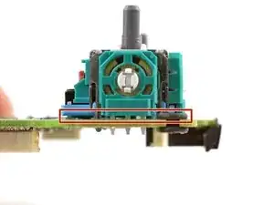
Insert the tips of a pair of angled tweezers between the top edge of a potentiometer and the joystick frame.
-
Pivot the tweezers down to bend the top edge of the potentiometer away from the joystick frame.
-
-
-
Secure the motherboard with helping hands or a similar tool so that the potentiometer solder joints face up.
-
-
-
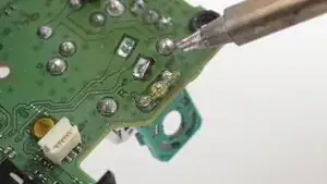
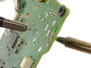
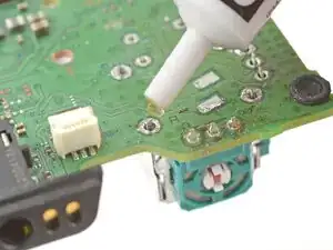
Press the soldering iron tip against a potentiometer joint to heat it.
-
Once the joint's molten, use a desoldering pump to suck away the solder.
-
Repeat the heating and sucking procedure a few times on the same joint to remove as much solder as possible. Be sure not to heat the joint longer than 15 seconds at a time.
-
-
-
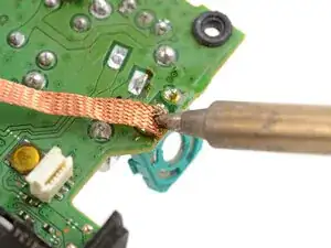
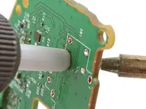
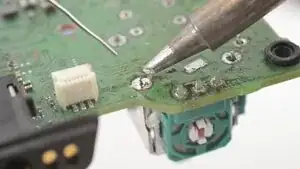
Apply flux to the solder joint.
-
Lay a piece of clean solder wick over the solder joint.
-
Press the tip of the soldering iron over the wick so that the residual solder melts and transfers into the wick.
-
Repeat the process with the remaining two solder joints.
-
-
-
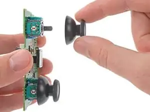
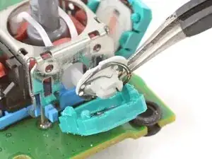
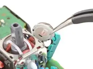
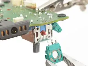
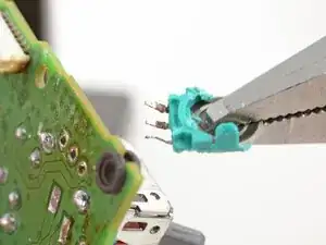
Remove the plastic components from the center of the joystick module.
-
Remove any loose pieces from the joystick module.
-
-
-
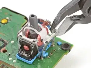
Use flush cutters to cut apart the top sections of the remaining frame walls, separating each wall into two pieces.
-
-
-
Secure the motherboard so that the solder joints face upward.
-
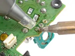
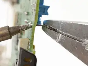
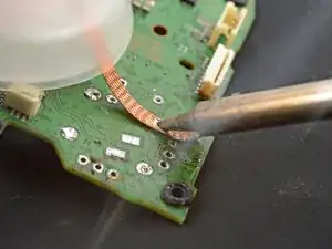
Use the soldering iron to heat a solder joint securing one of the frame anchors.
-
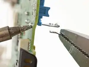
Once the solder is molten, use pliers to grab and pull the frame anchor out of its through-hole.
-
Repeat the procedure to remove all four anchor joints.
-
-
-
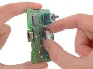
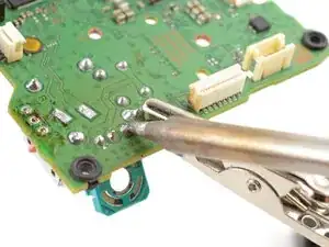
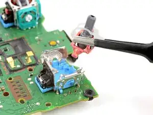
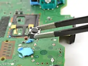
Slide the flat end of a spudger under the joystick module's plastic base.
-
Slowly pry up the base to bend and break it away from the motherboard.
-
Remove the plastic base.
-
-
-
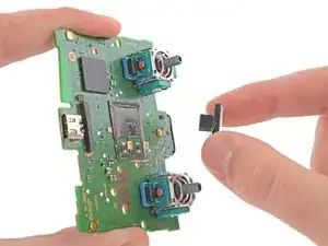
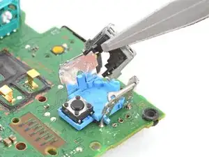
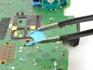
Use flush cutters and pliers to break and remove the plastic base remnants from the push-button.
-
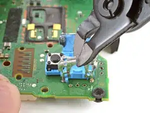
Use flush cutters to cut the four push-button pins securing it to the motherboard.
-
-
-
Use the soldering iron to heat a solder joint securing one of the push-button pins.
-
Once the solder is molten, use tweezers to grab the pin and pull it out of its through-hole.
-
Repeat the procedure to remove all four push-button pins.
-
-
-
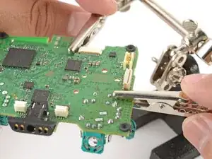
Secure the motherboard so you can access both sides of it.
-
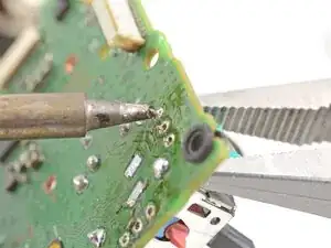
Use the soldering iron to heat one side of a through-hole.
-
Use a desoldering pump on the opposite side of the through-hole to suck up any remaining solder.
-
If needed, use solder wick to remove any residual solder.
-
Repeat this for all through-holes and both sides of the motherboard.
-
-
-
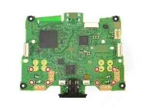
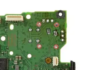
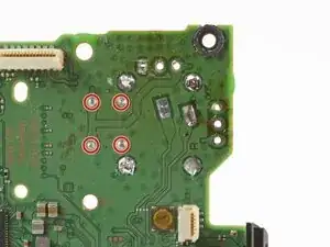
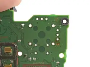
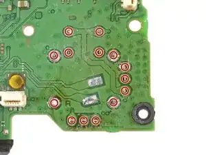
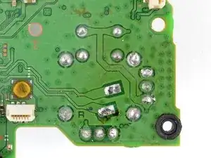
Visually inspect each through-hole and make sure they're not blocked by residual solder. If some holes look blocked, repeat the previous step to clear the blockage.
-
-
-
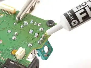
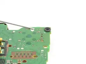
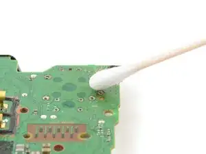
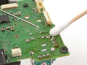
Apply a few drops of high concentration (>90%) isopropyl alcohol to the top side of the motherboard, where the new joystick module will sit.
-
Use a cotton swab or a soft brush and cloth to wipe away the flux residue.
-
-
-
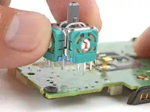
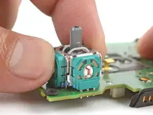
Place the replacement joystick module onto the motherboard so that all the pins thread through the through-holes.
-
Gently press the joystick onto the board so that the joystick sits flush with the board surface.
-
-
-
Flip the motherboard over and secure it so that you can solder the joystick module pins.
-
Apply flux to one of the frame anchors to prep it for soldering.
-
-
-
Check that the joystick module is still sitting flush on top of the motherboard (as shown). If it isn't, reheat the soldered pin and reposition the module.
-
-
-
Solder the remaining joystick module pins (14 total) to the motherboard. Apply flux as you solder to help create good bonds.
-
-
-
Apply a few drops of high concentration (>90%) isopropyl alcohol to the motherboard wherever you can see flux residue.
-
Use a cotton swab or a soft brush and cloth to wipe away the flux residue.
-
Visually inspect your work:
-
Make sure each solder joint looks well-formed.
-
Make sure no solder joints are shorting each other.
-


Congratulations! You've replaced the controller's joystick and, in the process, leveled up your soldering skills.
To reassemble the controller, go to this step and follow the instructions in reverse order.
You'll need to run the calibration tool to calibrate the new joystick.
Take your e-waste to an R2 or e-Stewards certified recycler.
Repair didn’t go as planned? Try some basic troubleshooting, or ask our Answers community for help.

Um comentário
Is there a calibration element post install of the new modules?