Introdução

  1. YrPVY3jAZMWoBkkN
    • The iPad screen has multiple small components mounted to the back of it:

    • The top sensor assembly

    • Two magnets along the top edge

    • Three display cables

    • If the replacement screen includes all of these components, skip to this step. Otherwise, only transfer the missing components.

  2. wlTJClEcKVcNDvjF
    wlTJClEcKVcNDvjF
    AAVhpnxGGYDLDwpd
    • The top sensor assembly is composed of two sensors:

    • Microphone

    • Ambient light sensor

    • If your replacement screen comes with a top sensor assembly pre‑installed, skip to this step.

  3. vhlhIxRiraeOWOuL
  4. UQZYPgh5ks2ZUFeV
    UQZYPgh5ks2ZUFeV
    InjCCFQN1wQQgaEw
    2frMMTuhHqp5JLnb
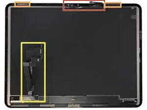
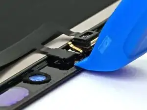
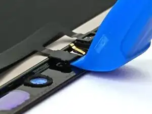
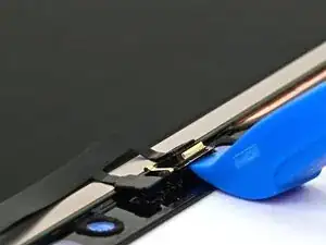
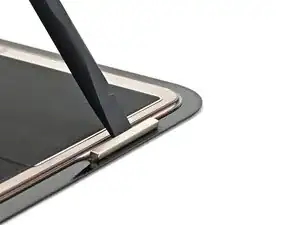
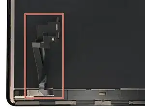
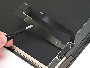
    • Slide an opening tool between the ambient light sensor and the screen.

    • Pry it up slowly to separate its adhesive. If it doesn't budge, apply more heat and try again.

  5. pbrcIHIX6p5FJDYD
    pbrcIHIX6p5FJDYD
    OsU6yVckr6UsgbkG
    61Ju3VrOOVPtw2Ux
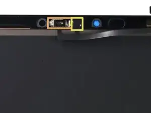
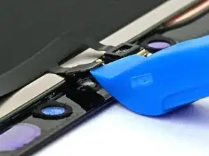
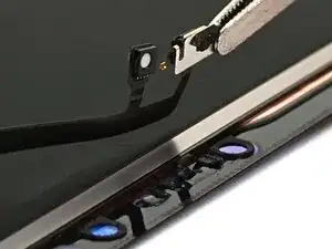
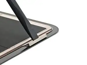
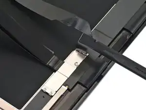
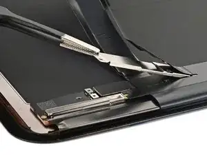
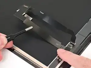
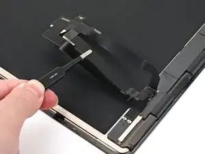
    • Use an opening tool to lift the microphone and separate the adhesive securing it to the screen.

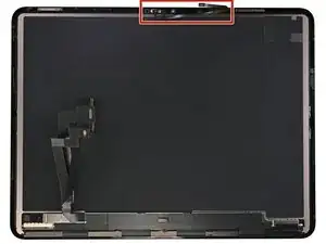
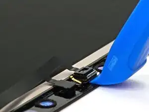
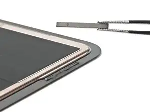
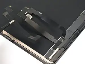
    • Lift the entire top sensor assembly to separate it from the screen.

  6. tWATIHGWLGSfuLbU
    tWATIHGWLGSfuLbU
    OXoFftg5TS6JtBOR
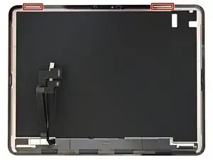
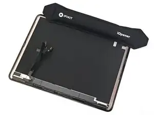
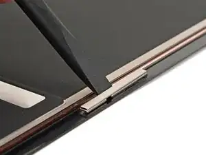
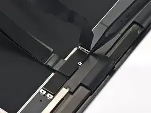
    • The iPad screen has two magnets along the top edge. These are used for accessories like cases.

    • If the replacement screen comes with magnets pre‑installed, skip to this step.

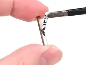
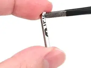
    • Mark the magnets with a marker so you know which orientation to install them in on the replacement screen—they won't work if installed incorrectly.

  7. ICLZBDHYfFIAcuHu
  8. NoccmpoXPwcSPRPU
    NoccmpoXPwcSPRPU
    wClDpAjP3h1VpCfY
    XIbMb34HB4aBomBj
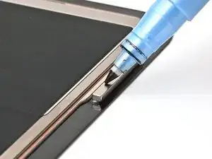
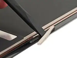
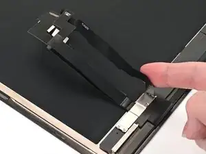
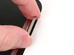
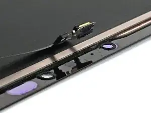
    • Insert the flat end of a spudger between the raised portion of the screen and the magnet.

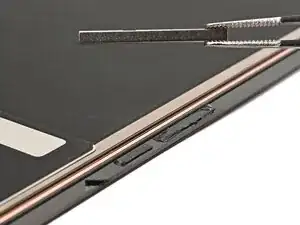
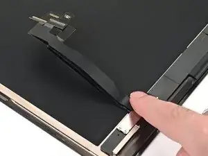
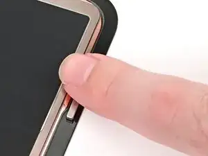
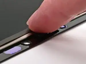
    • Push the magnet towards the top edge of the screen using slow, steady force until it's free.

    • Set the first magnet to the side, ensuring it remains in the same orientation.

  9. ZKDlTYffuXAgi64O
  10. bOVUTyB3ROv3vXeH
    bOVUTyB3ROv3vXeH
    rsonXuRFwA5kXhl3
    QMZusvte22AkmqXW
    • Repeat this process to remove the second magnet from the screen.

  11. q65PfH2JUo5Qdw6S
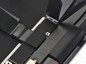
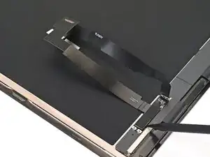
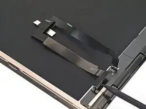
    • The screen contains three cables on the back: one for touch, one for display, and one for power (with two press connectors).

    • The touch and display cables are modular, and need to be transferred to the replacement screen in the following steps.

    • If your replacement screen has all three cables pre‑installed, skip to this step.

  12. sPVMPWMFaGTWgQ3Q
    sPVMPWMFaGTWgQ3Q
    JCHgJPSCBneuoPYH
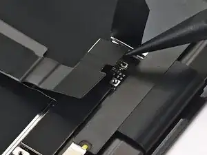
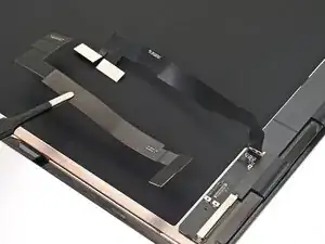
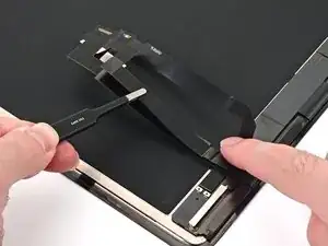
    • Use your finger or a spudger to lift the screen's power cable off the screen cable cover.

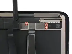
    • Use a JCIS or JIS 00 screwdriver to remove the three 1.2 mm‑long screws screws securing the screen cable cover.

  13. ThRXqnoDV1FcbbRI
    ThRXqnoDV1FcbbRI
    WRyNvnFVYXd5YQEe
    Mh4I4HdRpYOPp1hq
    • Lift the screen cable bracket to a roughly 45‑degree angle and pull it off.

  14. r3lhFgDHIAiP2Fk2
    r3lhFgDHIAiP2Fk2
    HgFIgKHmgprVD2hI
    Kc6A1cUQ2WDy5Qxx
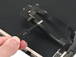
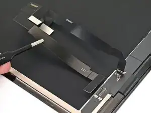
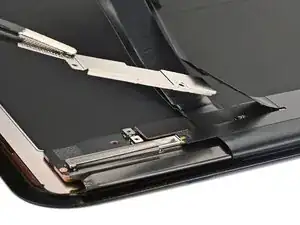
    • Fold the screen's power cable out of the way.

    • Use the point of a spudger to disconnect the screen's touch cable press connector.

  15. LmLm1AnsnfDnxjXU
    LmLm1AnsnfDnxjXU
    wFOpMHQQ6IwBW5NB
    • Use tweezers or your fingers to remove the touch cable.

  16. hUhhV2fOtmIESBcp
    hUhhV2fOtmIESBcp
    WwvUMS23q142JfU3
    3VSdofFfHEyB4QCD
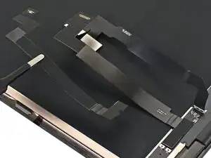
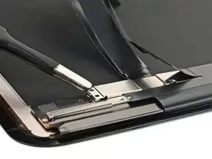
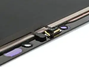
    • Use the point of a spudger to pry up and disconnect the display cable press connector.

    • Remove the display cable.

  17. v5ZbBlvMcXWO6vo5
    v5ZbBlvMcXWO6vo5
    WqZcqcxfQyVZA2KG
    r2DQ1PKdxrbvpGSw
    • Align the display cable press connector over its socket on the replacement screen.

    • Use your finger or the flat end of a spudger to press the connector into place.

  18. eZVyht6yZqROQfKP
    eZVyht6yZqROQfKP
    evAGUDXxCJb4NCRe
    ICHOoQa6U5iiWZZG
    • Repeat this process to connect the touchscreen cable press connector.

  19. pdKyNaw2GESfCXGo
    pdKyNaw2GESfCXGo
    V3ZJ16R1VbKUML6x
    J4CUV6QVJW1TVsCX
    • Install the screen bracket at a roughly 45‑degree angle and set it onto the cables.

  20. BtidWFsJn2ltHRgI
    • Use a JCIS or JIS 00 screwdriver to install the three 1.2 mm‑long screws screws securing the screen cable cover.

  21. CNGtmqnZFVJBbe2H
    CNGtmqnZFVJBbe2H
    hLxfMbcRAmLMHT2r
    • Fold the power cable down so it sits on top of the screen cable cover.

  22. aaqwBYVXWvaPQHuG
    aaqwBYVXWvaPQHuG
    uoFTMoyKQYejcqQU
    akm2rNZtG6HYiYDk
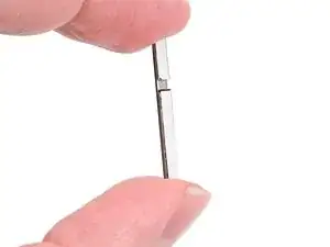
    • Install 2 mm‑wide strips of thin, double‑sided tape to the underside of both magnets.

    • Leave the adhesive backing in place for now.

  23. tNkSD1IICseh2AJb
    tNkSD1IICseh2AJb
    gnwmPP6JyMvJyefh
    • Use a marker to mark 23 mm from the left edge and 2 mm from the top edge of the screen.

  24. mPF4EUr4wGUw1vUH
    mPF4EUr4wGUw1vUH
    WeJgLGbVHipJxvdk
    PZEcM5YBuSYYfMYc
    • Remove the adhesive backing from the first magnet.

    • Align the first magnet with the marks you made in the last step, and set it into place.

    • Press on the magnet with your finger to help the adhesive bond.

  25. Z4nKepfxRVuHcPGZ
    Z4nKepfxRVuHcPGZ
    t45DT2XyKgSYjThC
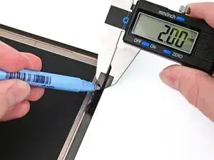
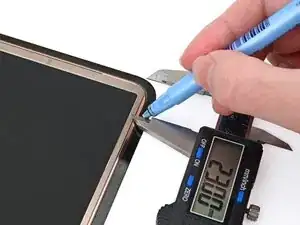
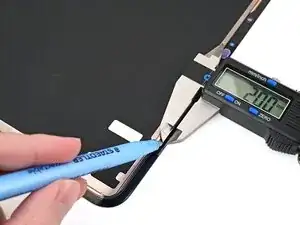
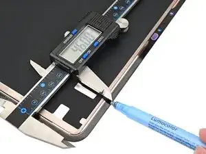
    • Repeat this process to install the second magnet 46 mm from the right edge and 2 mm from the top edge of the screen.

  26. HhwHdonBTH6stxPE
    HhwHdonBTH6stxPE
    GwICyluDUQKLnsZL
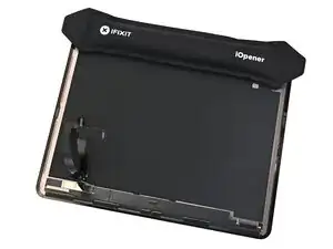
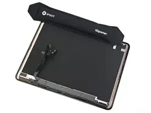
    • Heat an iOpener and set it on top of both magnets for two minutes. This will help the adhesive bond.

    • You can also use a hair dryer or heat gun to lightly heat each magnet to help the adhesive bond.

  27. aPAAZmCbvfGjfo5d
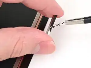
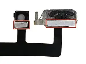
    • Use tweezers to reposition any adhesive that may have covered the ambient light sensor (white circle) or microphone (black mesh). The adhesive should go around the sensors, not cover them.

    • If the adhesive was damaged or stayed with the old screen, replace it with a 1 mm wide strip of thin, double-sided tape along the sensor's bottom border.

  28. GewYNReuGS1kjQJA
    GewYNReuGS1kjQJA
    IdTFDVgc5FOYFbdW
    T1XMHHj1aTnQbMMd
    • If you applied fresh adhesive, or if your part came with new adhesive, remove the liners now.

    • Align the microphone and ambient light sensor with their cutouts in the screen.

    • Press the microphone and ambient light sensor down for 10 seconds each to give the adhesive time to bond.

Nick Schultz

Membro desde: 24/03/24

45909 Reputação

0 comentários