Introdução
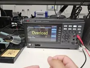
If your Keysight N2142A BNC probe connector has started reading 0 when you read voltages and overload when you read resistances, use this guide to diagnose the resistor burn out and replace it.
The BNC probe is used to interface between circuits and Multimeters or Oscilloscopes and is used for measuring voltages, resistances, and currents.
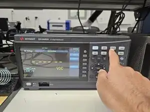
Before beginning this guide ensure that the Multimeter/Oscilloscope is in the correct mode to measure Voltage/Current/Resistance. It is best to try the probe with multiple Multimeters/Oscilloscopes to determine whether the issue is with the probe or the device.
This guide will require soldering and deconstruction with a screwdriver, so make sure that you feel comfortable with soldering and hand tools before beginning. You can follow this guide to learn how to solder.
Fully disconnect the probe from both the Multimeter/Oscilloscope and the circuit before beginning this guide.
-
-
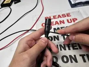
Insert a spudger between the rubber portion of the cable and the plastic casing.
-
Slowly work the spudger around the cable while twisting in order to pry the rubber away from the plastic casing.
-
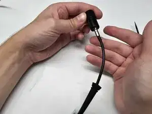
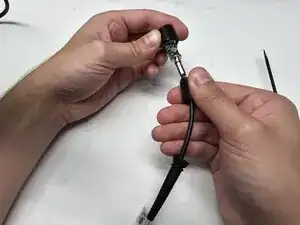
Once the rubber is separated from the plastic casing, slide the plastic casing away from the head of the cable.
-
-
-
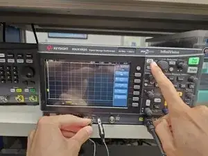
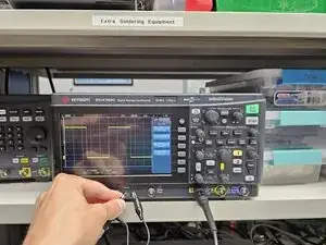
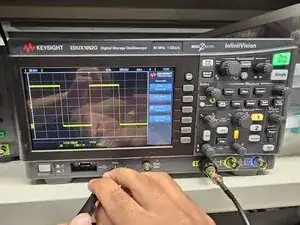
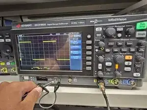
Plug the BNC probe into a oscilloscope and connect the probe leads to the test connections located under the screen.
-
Press the autoscale button while holding the connections in place.
-
-
-
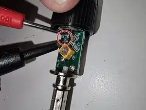
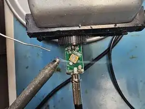
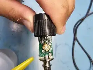
Use a vice to hold the probe in place while soldering.
-
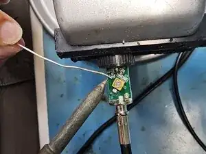
Add solder to both sides of the resistor.
-
Heat up the solder on one side of the resistor. Once you see the solder start to melt, immediately start heating up the solder on the other side of the resistor until you see the solder starting to melt. Repeat until the resistor is removed.
-
-
-
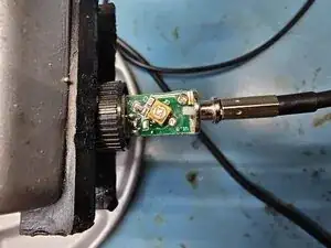
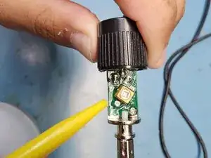
Use tweezers to hold the new resistor in place.
-
Add solder to the tip of your iron.
-
Solder on one side of the resistor. After one side is fixed, you can stop using the tweezers, and then solder on the other side of the resistor.
-
-
-
Use the oscilloscope to test the cable. Follow the same procedure as in step 2.
-
If the repair has worked, you will now see a square wave display on the screen.
-
-
-
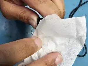
Spray the circuit board with Isopropyl Alcohol to clean it.
-
Gently wipe down the circuit with Kim Wipes. Do not use regular cloth to avoid lint build up on the circuit board.
-
-
-
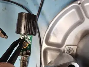
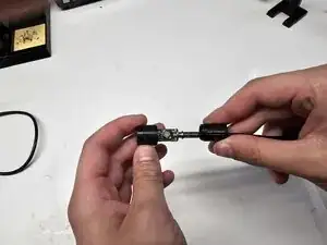
Slide the plastic casing back over the circuit board. Ensure that the small hole in the top of the casing lines up with the screw on the capacitor.
-
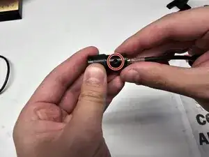
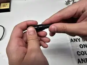
Slide the rubber neck of the cable back on. Ensure that there is no gap between the rubber neck and the plastic casing.
-


Congrats on completing this guide! You have helped reduce the toxic waste contribution from discarded lab equipment.