Introdução

Use this guide to replace the motherboard in your Kobo Libra Colour (model N428B) eReader.

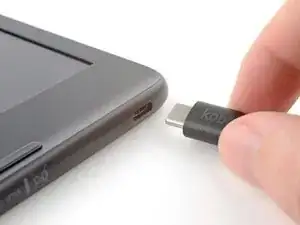
Important: There are two Libra Colour versions: N428 and N428B. Check your eReader's model number (printed on the edge of the device with the USB‑C port) before starting this guide. This guide is for the N428B model.

The charging port is soldered to the motherboard, so you'll need to replace the entire motherboard if you want to replace the port.

After this repair, follow this guide to calibrate your eReader to your replacement motherboard. If you don't, you might experience "ghosting" or visual artifacts of the E ink.

Following this guide will remove your eReader's IP (Ingress Protection) rating, making it susceptible to water damage.

Kobo supports their eReaders with a warranty. If your device is still under warranty, Kobo may be able to help. Before starting a repair, review your warranty information or check support documentation.

Note: Some photos used in this guide are of different Kobo Libra models. Any slight visual discrepancies won't affect the guide procedure.

  1. GqxIiULncF21ENgO
    GqxIiULncF21ENgO
    EB6HnFSdo3HjgEtv
    fPKWpfBhwVB6DaXx
    • Drain your eReader's battery as much as possible before starting your repair. Ideally, it should be fully discharged.

    • Optionally, to drain the battery faster, navigate to MoreSettingsEnergy saving and privacy and set Automatically go to sleep after and Automatically power off after to Never.

    • When working on or near the battery, don't use sharp metal tools to avoid puncturing and shorting the battery.

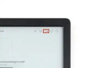
    • Unplug all cables and fully shut down your eReader.

    • Your screen should be black and say Powered off.

    Don't forget to remove the protective sheet from the replacement screen (as I did). Thanks for the manual, its working now again!

    Hans -

    Haha I second that! I nearly had a heart attack when I realized I hadn't removed the plastic film

    Arianna A -

  2. TPpxsLcsmgaPFxNF
    TPpxsLcsmgaPFxNF
    CT1XMaClc61CCTCI
    VmtBxMMmLknG1ZtT
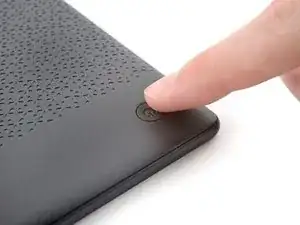
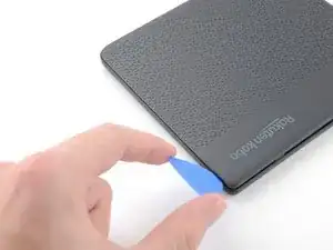
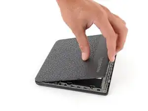
    • Flip your eReader over so the screen is facing down.

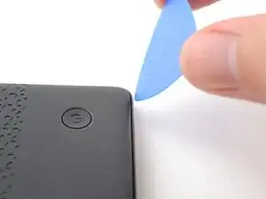
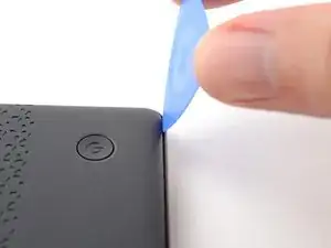
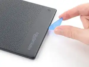
    • Angle an opening pick straight down, and insert its tip under the top right corner of the back cover, near the power button.

    • Push downward and pry up with the pick until you feel it slide between one of the clips and the frame.

    • You may have to test a few spots along the corner until the pick slides between one of the clips.

  3. 4Wyg6sI55X4XfZXn
    4Wyg6sI55X4XfZXn
    KW1XrUEr5GjSIh2q
    ZYracIWpbZtsDMfa
    • Slide the pick toward the bottom right corner to release the clips along the right edge.

  4. ew2UsHdvphafIIOT
    ew2UsHdvphafIIOT
    gUxJCgS4liVAJQuQ
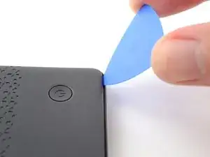
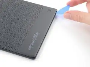
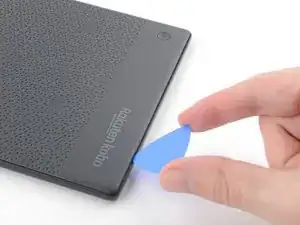
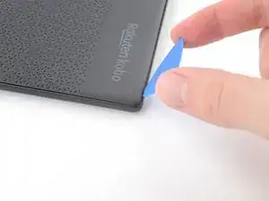
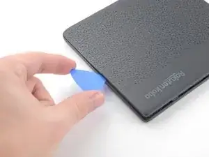
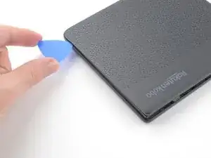
    • Angle the pick flat under the back cover and rotate it around the bottom right corner to release its clips.

    • If you're having trouble, try twisting the pick to lift the corner clips out of their slots.

  5. JLZk2HqRxSpTumot
    JLZk2HqRxSpTumot
    DHybTPoDNsLASolZ
    YHoXY4TvTwMDS2tr
    • Slide the pick toward the bottom left corner to release the clips along the bottom edge.

  6. eELw4HIs3in5FnBH
    eELw4HIs3in5FnBH
    Fld1qdbbZ4gHFGBE
    yftQSCXd2Pv3x5fS
    • At this point, you should be able to grip the back cover and release its remaining clips. If not, slide a pick under the perimeter of the back cover until you can grip an edge.

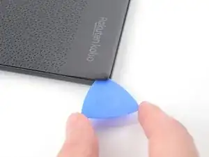
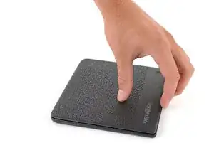
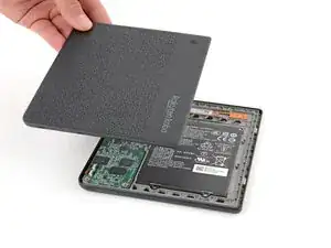
    • Grip the right edge of the back cover and lift it away from the eReader to release the remaining clips.

    • Remove the back cover.

    • During reassembly, align the back cover over the eReader and press along the perimeter until all its clips snap back into place.

  7. OeLbFETLaFUo2GXh
    OeLbFETLaFUo2GXh
    2Ydyo6TikdYnhfIV
    SEEQeLjowJyhH2R4
    • The entire surface of the eReader's internals is covered in a thin, plastic-like waterproof coating. Keep the following in mind as you continue disassembly:

    • While this won't hurt your device, removing the coating compromises the device to potential water damage.

    • The coating is brittle and can flake into many small pieces. Heating the coating helps, but working with it is still a time-consuming process.

    • Depending on your repair, you might have to remove the coating from ZIF connectors and their cables.

  8. iPT2cBmrPoKZgVBd
    iPT2cBmrPoKZgVBd
    RGJO1qP3a5uC6ENO
    • Use a spudger to pry up and disconnect the battery press connector.

    • Don't pry against the motherboard, as you risk breaking small, surface-mounted components.

    • Your E-ink screen will continue to say Powered off even after disconnection—this is normal!

  9. KhtXWJfWyKeABAQy
    KhtXWJfWyKeABAQy
    E5BEYifAEK6IXpwR
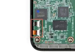
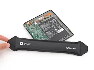
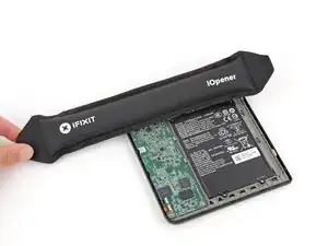
    • Heat an iOpener and lay it on the digitizer cable ZIF connectors for 90 seconds to soften the coating.

    • Alternatively, you can use a hair dryer or a heat gun for 30 seconds.

  10. LEj1STqSBuwFEBuL
    LEj1STqSBuwFEBuL
    BZIpEPUMngsLijtH
    UOKcnpDNIxfFoTSQ
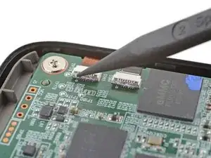
    • Use the tip of a spudger to scrape the coating along the ZIF connectors' black locking tabs—enough so you can grab clumps of it with pointed tweezers.

    • Use pointed tweezers to peel off the coating around the black locking tabs and their hinges on the ZIF connector.

    • If the coating becomes too brittle and hard to peel off, reheat the connectors and try again.

    • This is a meticulous process! Failure to remove enough of the coating could damage the locking tab during disconnection, so take your time!

  11. sAoSoFAmLxeveJpO
    sAoSoFAmLxeveJpO
    26h1mxZyjej3bOji
    KvEtCedNhRnDBnon
    • Use the point of a spudger to lift up the locking tabs on the ZIF connectors.

    • The locking tabs should be nearly vertical when unlocked. If not, remove more coating until the tabs can move freely.

  12. 6bdeDIYWWAiCOsIq
    • Apply a heated iOpener to the digitizer cable ZIF connectors for 90 seconds to soften the coating.

    • Alternatively, you can use a hair dryer or a heat gun for 30 seconds.

  13. UELbdkWGUYyWymyG
    UELbdkWGUYyWymyG
    G52VM3ptB2lEmZum
    XrVnDQaAJ2nRItPJ
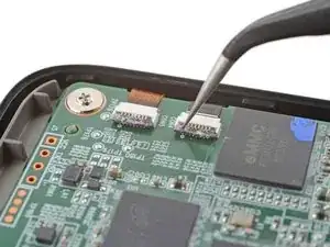
    • Slide one arm of a pair of pointed tweezers underneath the cables to separate the coating securing them to the motherboard.

    • You only need to separate enough coating so you can grip the cables with blunt nose tweezers.

  14. DAJBupISMixnTqQU
    DAJBupISMixnTqQU
    5dPFxM4KGRDeUFGE
    2SKfQtUtGuDtiCWf
    • Because of the awkward angle, this step requires some patience to avoid tearing the cables. Work slowly and apply heat regularly.

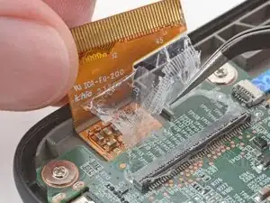
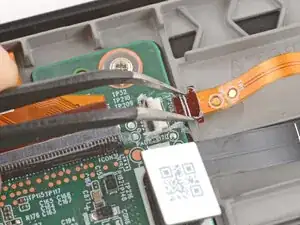
    • Use blunt nose tweezers to pull the cables away from their ZIF connectors slowly and steadily at a level angle to separate the coating.

    • Gripping the tweezers closer to the tip can help get a tighter hold on the cables.

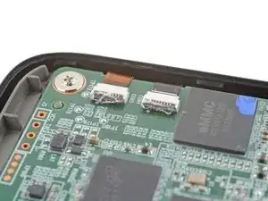
    • Keep pulling on the cables until they're completely disconnected.

    • During reassembly:

    • Inspect the ends of the cables and the ZIF connectors for any remaining coating that could prevent a good connection.

    • Peel off the coating, heating the cable and the ZIF connectors when the coating becomes too brittle.

    • It doesn't have to look pretty! You just need to remove enough coating to have the cables sit properly in their connectors.

  15. gACajbEcPfVWRZxy
    gACajbEcPfVWRZxy
    vKKhpmxLFXmKLi34
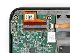
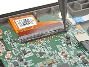
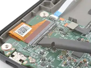
    • Apply a heated iOpener to the display cable ZIF connector for 90 seconds to soften the coating.

    • Alternatively, you can use a hair dryer or a heat gun for 30 seconds.

  16. UtVeqLH6AdAfTbVe
    UtVeqLH6AdAfTbVe
    Mmn1rkC6b5kYVQ11
    qNd6cgBrLNpgMjXu
    • The display cable ZIF connector is larger and requires a different procedure to disconnect properly.

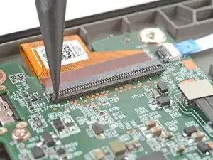
    • Use the tip of a spudger to scrape the coating along the ZIF connector's black locking tab—enough so you can grab clumps of it with pointed tweezers.

  17. 4KjrhswKDaeBeXQe
    4KjrhswKDaeBeXQe
    GjBifZ3nAinFqTHf
    GWLWM1OdKgFkxYlJ
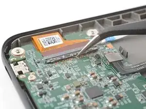
    • Use pointed tweezers to peel off the coating around the locking tab and its hinge on the ZIF connector.

    • If the coating becomes too brittle and hard to peel off, reheat the connector and try again.

    • This is a meticulous process! Failure to remove enough of the coating could damage the locking tab during disconnection, so take your time!

  18. QYovDlKDT466FnSm
    QYovDlKDT466FnSm
    IE3RJEt2m2p6nXL4
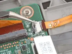
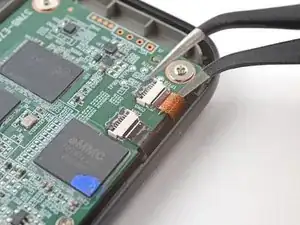
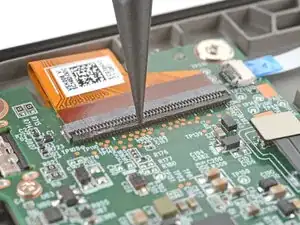
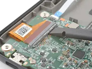
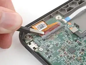
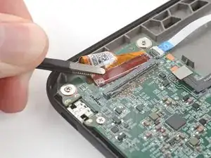
    • Use the flat end of a spudger to gently pry along the length of the locking tab to separate any remaining coating.

    • Don't pry hard at the corners of the locking tab to avoid snapping it.

  19. Ddaao21Gla6uQldQ
    Ddaao21Gla6uQldQ
    ZU3lILnbjsRquCFP
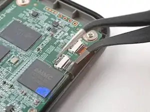
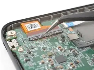
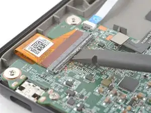
    • Insert the flat end of a spudger under the middle of the locking tab and lift to unlock it.

    • The locking tab should be nearly vertical when unlocked. If not, remove more coating until the tab can move freely.

  20. IhZLSeZkwP23JubO
    IhZLSeZkwP23JubO
    ZxOQ6arobUvXOt6T
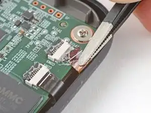
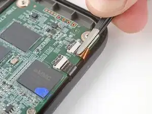
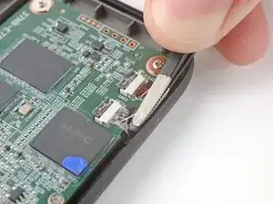
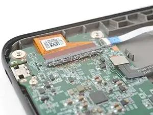
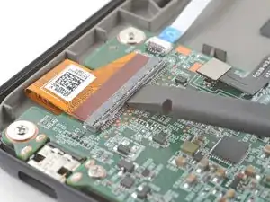
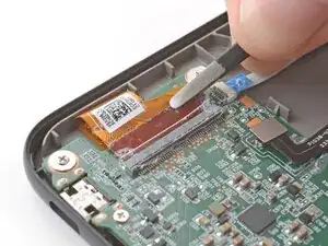
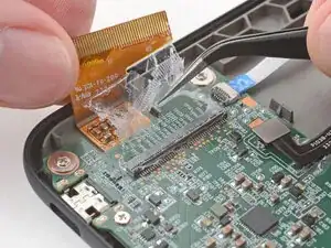
    • Use blunt nose tweezers to grip the corner of the display cable closest to the charging port.

    • Pull the cable away from the ZIF connector slowly and steadily at a level angle to separate the coating at the corner.

    • If you're having trouble, try rocking the cable side-to-side while pulling.

    • Gripping the tweezers closer to the tip can help with getting a tighter hold on the cable.

  21. THhKF1Yu1nKODlMn
    THhKF1Yu1nKODlMn
    MaG5KhnODSgrwxiR
    VAvZDGNvOXXmOVcX
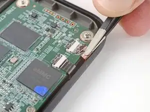
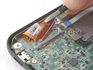
    • Repeat the previous step for the other corner until the entire cable is disconnected.

    • Lift up the cable and peel off any remaining coating holding it to the motherboard.

    • During reassembly:

    • Inspect the ends of the cable and the ZIF connectors for any remaining coating that could prevent a good connection.

    • Peel off the coating, heating the cable and the ZIF connector when the coating becomes too brittle.

    • It doesn't have to look pretty! You just need to remove enough coating to have the cable sit properly in the connector.

  22. LQs3oSCHd2IEUCme
    LQs3oSCHd2IEUCme
    gKCRAOMoMTkgGLCw
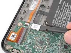
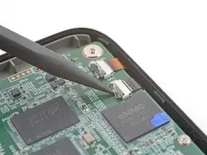
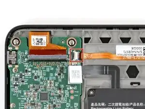
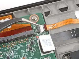
    • Heat an iOpener and lay it on the power button ZIF connector (near the top right corner of the motherboard) for 90 seconds to soften the coating.

    • Alternatively, you can use a hair dryer or heat gun for 30 seconds to soften the coating.

  23. gmbUTPSscbVQufjk
    gmbUTPSscbVQufjk
    IyScj4Dnp6wRMmgJ
    p2ogPbMX5DDKADVB
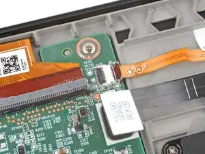
    • Use the tip of a spudger and pointed tweezers to scrape and remove the coating from the ZIF connector's locking tab and cable.

    • If the coating becomes too brittle and hard to peel off, reheat the power button board and try again.

    • This is a meticulous process! Failure to remove enough of the coating could damage the locking tab during disconnection, so take your time!

  24. tGyXVT4iNdJAqlCT
    tGyXVT4iNdJAqlCT
    1aUPlFLlYnTssQpC
    haVq4VQLnqMvNBiW
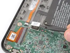
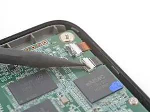
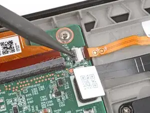
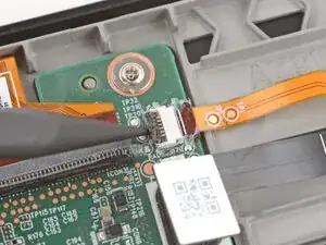
    • Use the tip of a spudger to lift up the locking tab on the power button ZIF connector.

    • The locking tab should be nearly vertical when unlocked. If not, remove more coating until the tab can move freely.

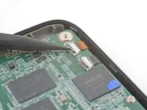
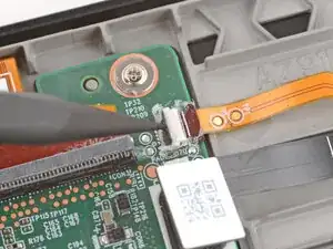
    • Use angled tweezers to push the cable fully out of its socket, pushing on the small "arms" near the head of the cable.

    • If you're having trouble, you can use your fingers to gently pull on the cable—don't grip the cable with tweezers or you may damage it.

  25. nDx2ZfKjMXAmEUWr
    nDx2ZfKjMXAmEUWr
    KgnWfxeT6jwrbAAX
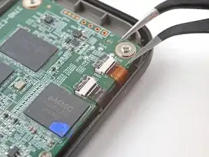
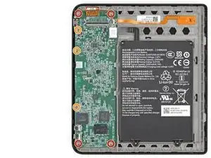
    • Use a Phillips screwdriver to remove the seven screws securing the motherboard:

    • Four 2.4 mm‑long screws

    • Three 3.9 mm‑long screws

  26. LGsayIeeTmhTF4Ny
    LGsayIeeTmhTF4Ny
    crdrGVbCJN6NZsyf
    PrKGZQWFhNelyVSf
    • Four tabs secure the motherboard in place—two plastic ones on the outer edge, and two metal ones near the battery.

    • Be very careful not to damage any of the small, surface‑mounted components on the motherboard during this step.

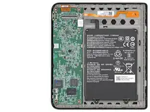
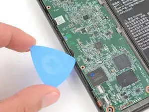
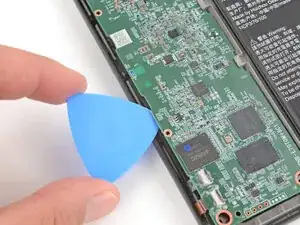
    • Insert the tip of an opening pick betwen the motherboard and the plastic buffer beneath it, near one of the plastic clips on the outer edge.

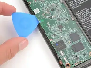
    • Gently twist the pick to release the clip.

    • Repeat the process to release the other plastic clip.

    • During reassembly, gently press down near the center of the board's outer edge to engage the two plastic clips.

  27. XWTFNtEmJtGZA3VD
    XWTFNtEmJtGZA3VD
    jaQOHn1UBxSE4xNE
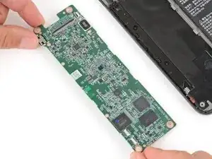
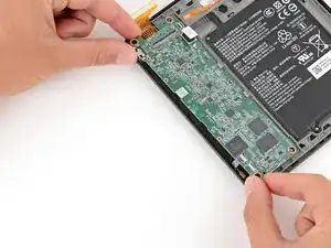
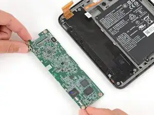
    • Grip the outer corners of the motherboard with your fingers and slide the board over the left edge to remove it.

    • Don't lift the board, or the tabs near the battery may damage it.

    • During reassembly:

    • Slide the board into place so the inner edge (opposite the USB‑C port) goes under the two metal tabs.

    • Lower the board into its recess, making sure no cables get stuck under the board. Ensure the corner screw holes go over their alignment posts.

    • If a cable gets stuck, use a spudger to gently pull it out. If you're having trouble, remove the board and try again.

Conclusão

To reassemble your device, follow these instructions in reverse order.

Remember: after repairs, your eReader is no longer IPX8 waterproof.

Compare your new replacement part to the original part—you may need to transfer remaining components or remove adhesive backings from the new part before you install it.

Make sure each of your device's main functions still work, e.g., LED backlight, touch, page-turn buttons, Wi-Fi, etc.

Take your e-waste to an R2 or e-Stewards certified recycler.

Repair didn’t go as planned? Try some basic troubleshooting, or ask our Answers Community for help.

Spencer Day

Membro desde: 14/09/22

165254 Reputação

0 comentários