Introdução

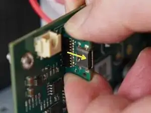
Replacement of the USB daughterboard on any Kaffelogic Nano or Nucleus Link coffee roaster with a D or P prefix serial number.

  1. bEdI12xSfVQDKaCd
    bEdI12xSfVQDKaCd
    keWYfIuvFMvyWLWV
    • Remove the 6x 2.5mm Hex screws on the left and right side of the roaster.

    • Take care not to damage the buttons while maneuvering the front panel, with all six screws removed it may fall away.

  2. MhQ4bjGDjKieVDbY
    MhQ4bjGDjKieVDbY
    Nqrlq6TYIlRCEmPp
    • Hold the front panel steady while removing the plastic top/closure.

  3. JttMZ1MrHIv3w14y
    • Pull away the front panel carefully.

  4. xlnoDyLNHUxvifcH
    xlnoDyLNHUxvifcH
    BA3QijfXOOId6nAg
    3OUB1gVyYEkIiqKS
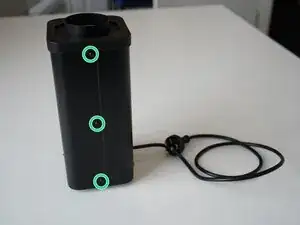
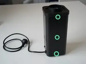
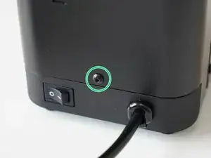
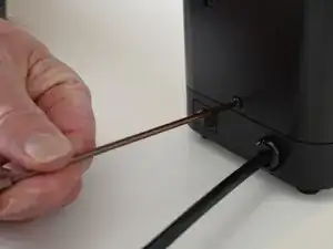
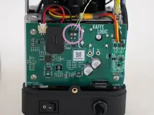
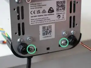
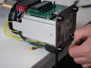
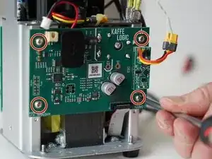
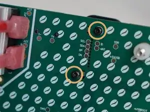
    • Remove the last 2.5mm Hex screw securing the rear panel.

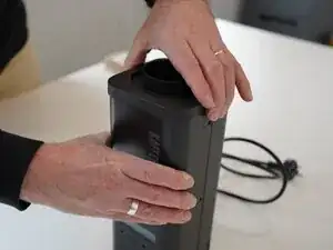
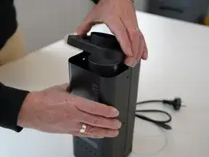
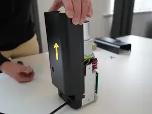
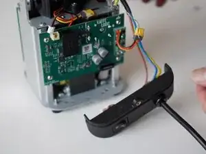
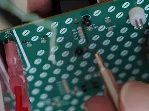
    • Pull up on the rear panel to remove it from the roaster.

  5. id1Iu26FpOZgSFqK
    id1Iu26FpOZgSFqK
    bgPTsWYHJElkbeUh
    • Set the panels aside somewhere safe and bask in the beauty of your naked roaster.

  6. PaRjZ2QasSXgVFcZ
    PaRjZ2QasSXgVFcZ
    QPGxpmc46PBiUpgX
    cpDdlMj4HXDwCYFM
    • Use a 2.0mm slotted screwdriver to remove the thermocouple wires from the PCB-A

  7. ZFPKUNVVmHYiqQ6Y
    ZFPKUNVVmHYiqQ6Y
    UJCkoyF3VhLXESGW
    • Disconnect the motor cable, this may take some wiggling.

    • Refrain from using pliers or metal tools on this connector, as the plastic insulation can be damaged.

  8. yhZQRTiPqysjyNo6
    yhZQRTiPqysjyNo6
    bQXCMLInAuViRFNJ
    • Pull upwards on the SSR signal connector to remove it.

  9. lmunQGxVkx2jDLj2
    lmunQGxVkx2jDLj2
    poCEb3unXWLLaOwa
    XD5NDmMMEb3oETLi
    • Remove the 2x 2.5mm Hex screws securing the cable carrier to the base.

    • Be careful not to lay the roaster on its front as the buttons can be damaged or broken off.

  10. FHMKHmWBUYZPr12J
    FHMKHmWBUYZPr12J
    butDUX6VgGeYTLhv
    • Gently remove the ribbon connector.

  11. IUQEiOaTYtpM3p3M
    • Unscrew the 4x PH2 PCB screws.

    • These screws are captive to the PCB.

  12. QQxAE3wGyxFpLKb5
    QQxAE3wGyxFpLKb5
    GERrWhIZ1AstkT51
    mutkSuSmNVVQ6RSh
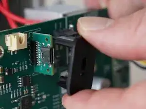
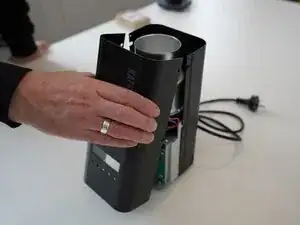
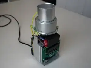
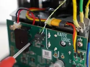
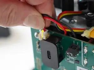
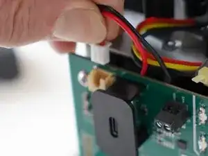
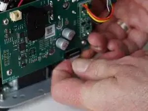
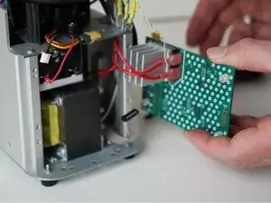
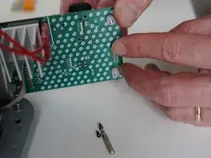
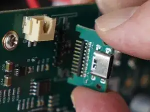
    • Pull the PCB away from the base assembly.

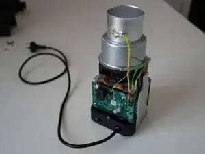
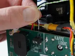
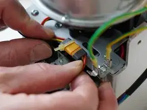
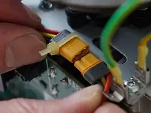
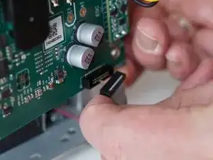
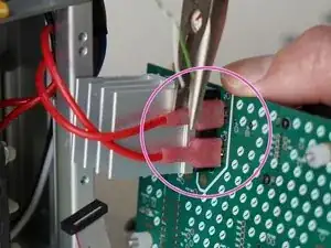
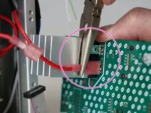
    • Use pliers to disconnect the transformer secondary wires from the back of the PCB

    • The transformer wires may be reconnected in either orientation. If you are replacing the USB daughterboard, you can choose to leave these wires in place.

  13. mJyCElwTML3tWhIv
    mJyCElwTML3tWhIv
    dofU5bbP3glqaJfF
    3Ss3ivCyxj33xYCV
    • Remove the 2x 1.5mm hex screws securing the plastic USB shroud.

  14. 6WI321jMkOX3BrVE
    • Slide the plastic shroud away from the PCB

  15. UTrASXH1SMGLpL3P
    UTrASXH1SMGLpL3P
    PfZNJEHQBB6RtPtZ
    • Pull away on the daughterboard to remove it from the main PCB.

Conclusão

To reassemble your device, follow these instructions in reverse order.

Kaffelogic

Membro desde: 23/07/25

2356 Reputação

0 comentários