Introdução

Replacement of the mainboard on any Kaffelogic Nano or Nucleus Link coffee roaster with an A, B, C or N prefix serial number.

  1. nfvSoTpnU4ksHcg6
    nfvSoTpnU4ksHcg6
    6MBXn1MgnMby6MAZ
    • Remove the 6x 2.5mm Hex screws on the left and right side of the roaster.

  2. qHiOtnAKcXjbaGoV
    qHiOtnAKcXjbaGoV
    OTbSwheRLDR1RpCH
    • Hold the roaster steady while removing the plastic top/closure.

    • Panels may spring apart slightly once removed.

  3. 5HgQGHsOcGRtWytG
    5HgQGHsOcGRtWytG
    YsnjyWOviUPEAgsT
    eljWHIrc23oQeaUH
    • Remove the 4x 2.5mm Hex screws on the bottom of the roaster.

  4. bokl2m3pNTLZsgaj
    bokl2m3pNTLZsgaj
    vu3RZpeDAwj1xhOk
    bUSiSNcKCwSERKhY
    • Pull away the front panel carefully.

    • Take care not to damage the buttons while maneuvering the front panel.

  5. CjFpLJRcjntXBWtF
    CjFpLJRcjntXBWtF
    U6CP2AwbVHaHnrnW
    Qasmpv1ohW2EYEcf
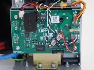
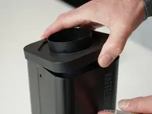
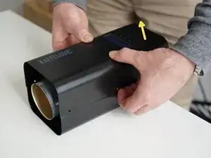
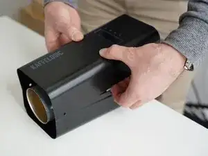
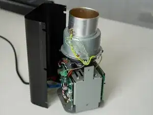
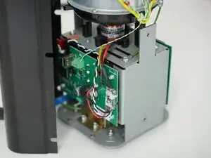
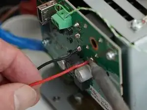
    • Stand the roaster up again and pull away the rear panel from the chassis to expose the remaining components.

    • The mains cable is routed through the panel and it will remain attached, place the panel in a soft bag if you wish to protect the paint throughout the rest of your repairs.

  6. 4JNyTINyjeOjhQDh
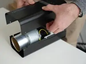
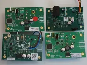
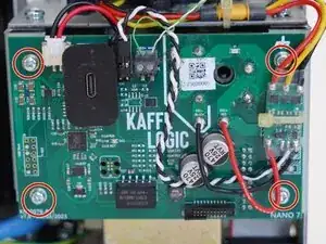
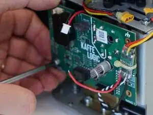
    • Boards may vary, the PCB in your roaster may not look like the one in this guide, but the steps should still match the general replacement process.

    • All replacement boards will have a USB-C connection. You will have to migrate any custom profiles on your USB stick to the onboard storage with Kaffelogic Studio.

  7. Ofj2F4N5jH5LChry
    Ofj2F4N5jH5LChry
    tvTCqaeAVnjLT3kV
    • Pull upwards on the SSR signal connector to remove it.

  8. Nb1tgteAAqjPp4YK
    Nb1tgteAAqjPp4YK
    gBxF1EWnnhNgVd24
    • Use a 2.0mm slotted screwdriver to remove the thermocouple wires from the PCB-A

  9. A5bPKpSYsVBEwniu
    A5bPKpSYsVBEwniu
    LbikJRtTtcXs6Mp6
    W3Dx3UDhIRIqhpkg
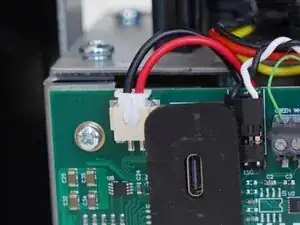
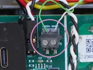
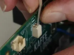
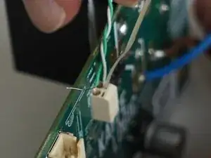
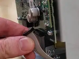
    • If your thermocouple connector looks like this, you will need to follow this step.

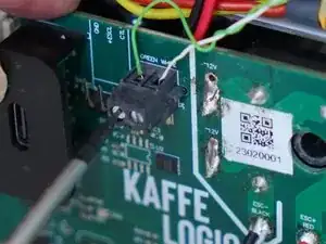
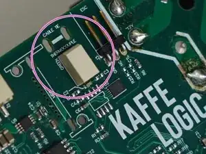
    • Use the end of a cable tie or very small plastic spudger to open the contact and remove your thermocouple wires. You may need to trim the cable tie end to fit into the slot.

  10. kNFOKrXjCWYjjYeu
    kNFOKrXjCWYjjYeu
    dvMlyKCcN13sV2cM
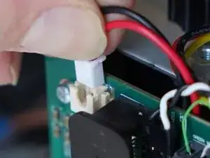
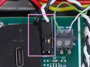
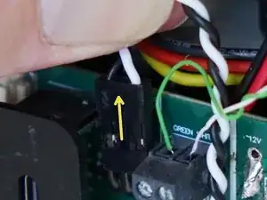
    • (Applicable to early models) Pull upwards on the motor controller signal connector to remove it.

    • Black wire to the left when replacing.

  11. KIYThQH4oVfgHAW4
    KIYThQH4oVfgHAW4
    GDP13NxSRD3RNJ5V
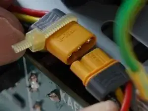
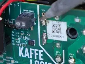
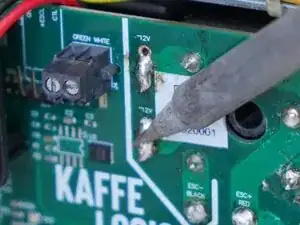
    • Unplug your motor if your roaster is fitted with a connector, otherwise de-solder the motor controller power.

  12. K6QZybeoES2eaEtL
    • Carefully pull on the ribbon cable to remove it.

    • Some boards have a larger cable on the other side of the PCB.

  13. DMUZg1pLBV2oOlUe
    DMUZg1pLBV2oOlUe
    TfaqsG6puWHTX5aY
    • Remove the 4x PH2 PCB screws.

  14. XrCvKP2iacUo1llu
    XrCvKP2iacUo1llu
    VMJqpQnSrrFaEVfY
    • Prepare your soldering iron and de-solder/reflow the two transformer wires to remove them.

  15. MKyoHCDrMjLxU1CZ
    MKyoHCDrMjLxU1CZ
    AZIYvRUenreOYBDe
    H6JZoIeKuLyRIGfB
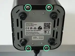
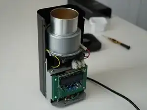
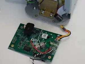
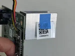
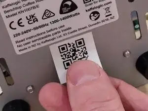
    • Your mainboard is now removed and ready for rework or replacement. Replace the serial code on the bottom of your roaster with the included QR label.

    • Head through to our wiki for instructions on recalibrating your fan speed and setting the voltage and element resistance after replacing the mainboard.

    • Nucleus Link anemometer calibration instructions can be found here.

Conclusão

To reassemble your device, follow these instructions in reverse order.

Kaffelogic

Membro desde: 23/07/25

2356 Reputação

0 comentários