Introdução
Follow this guide to replace a degraded battery in a right Nintendo Joy-Con 2 controller. If you need to replace the battery in a left Joy-Con 2, follow this guide instead.
The Joy-Con 2 uses JIS screws. If you use a non-iFixit Phillips driver in JIS screws, you'll risk stripping them.
If your replacement battery doesn't include adhesive, you'll need replacement adhesive or thin, double-sided tape to complete this repair.
-
-
Use a tri-point Y00 driver to remove the two 3.1 mm‑long black screws on the left edge of the controller.
-
-
-
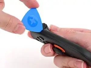
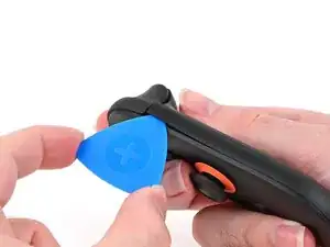
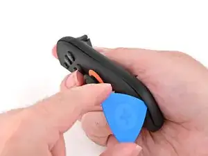
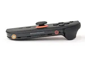
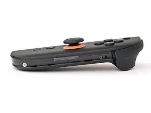
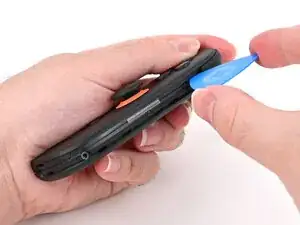
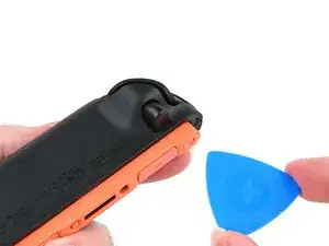
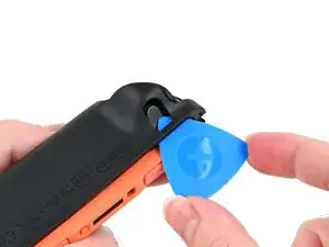
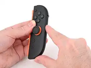
Insert an opening pick into the gap underneath the bumper button on the right side of the controller, with a point of the pick pointing downwards.
-
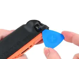
Pry up to slightly lift the plastic strip running across the right edge of the controller.
-
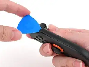
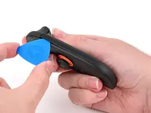
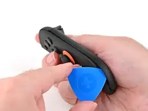
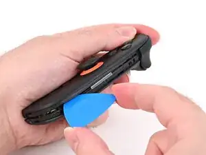
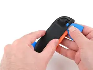
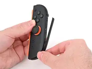
Slide the opening pick around to the front of the controller.
-
-
-
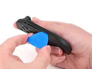
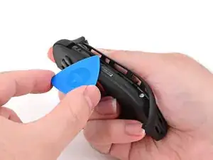
Slide the opening pick down the plastic strip to separate the clips and adhesive securing it to the controller's body.
-
-
-
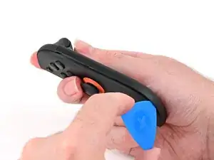
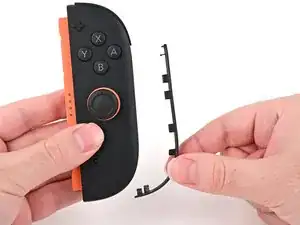
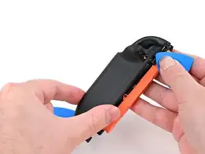
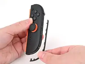
Pry up on the bottom edge of the plastic strip with slow, steady force.
-
Repeat this prying action along the length of the strip until it's fully detached.
-
-
-
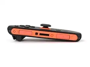
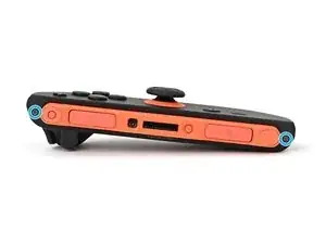
Remove the two screws on the right edge of the controller:
-
One 3.1 mm‑long tri-point Y00 black screw
-
One 3.0 mm‑long JIS 00 silver screw
-
-
-
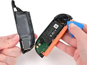
Insert an opening pick into the gap between the front and back halves of the controller on its right side.
-
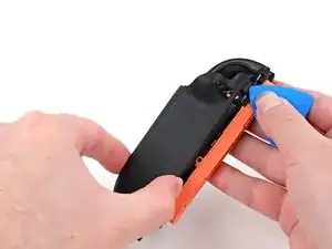
Slide the pick down the controller to disengage the clips.
-
Leave the opening pick at the bottom of the controller's right edge, just before its curve.
-
-
-
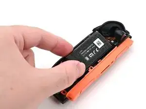
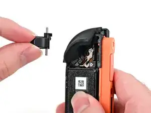
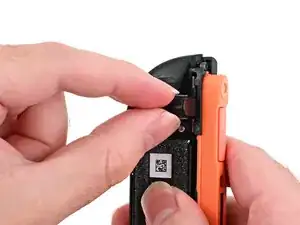
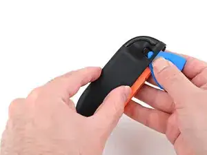
Hold the controller upside-down.
-
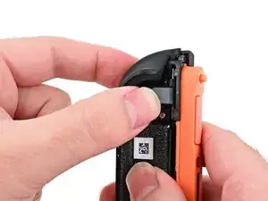
Insert a point of another opening pick next to the release button towards the top of the controller.
-
Use the opening pick to press the release button through the gap.
-
-
-
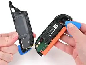
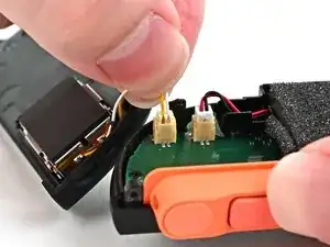
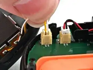
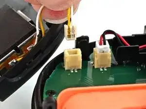
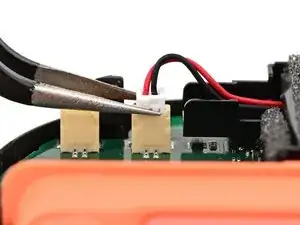
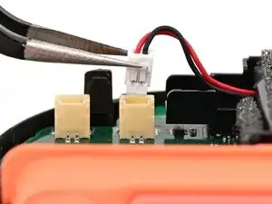
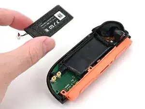
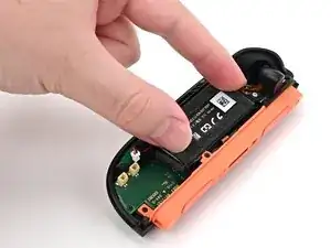
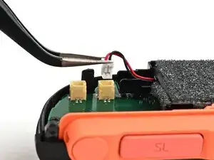
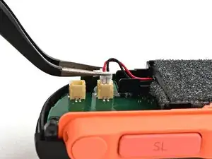
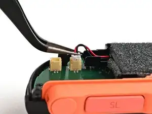
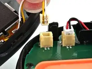
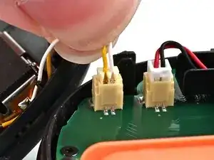
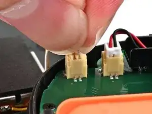
Firmly grasp the two wires (yellow and white) above the rumble motor connector, located at the bottom of the controller's board, and pull the beige connector out of its socket.
-
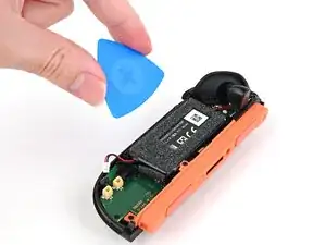
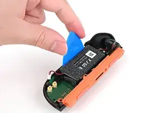
Remove the back cover.
-
-
-
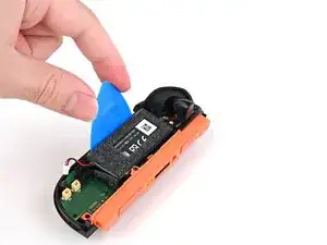
Use tweezers or your fingers to firmly grip the battery cable's white JST connector and pull straight away from its socket to disconnect it.
-
-
-
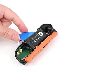
Insert a flat edge of an opening pick into the gap between the battery and the battery well.
-
-
-
Pry the battery up slowly with steady force to release the adhesive.
-
If you're using adhesive remover, follow these preparation steps first.
-
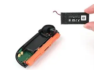
Remove the battery.
-
-
-
Congratulations on completing disassembly! The remaining steps will show how to reassemble your console.
-
-
-
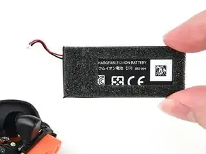
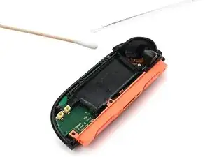
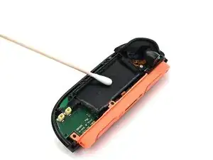
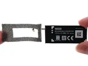
Use an opening pick or your fingernail to lift the foam off the battery by its adhesive, not the foam itself.
-
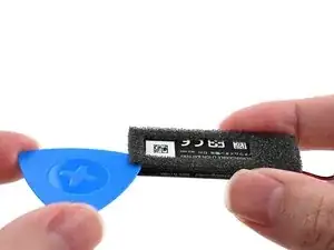
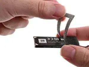
Carefully peel the foam sticker off the old battery. Avoid stretching or tearing the foam.
-
Apply the foam sticker to the new battery so the edges of the foam are aligned with the edges of the battery.
-
-
-
If your replacement battery came with adhesive pre-installed, peel off any adhesive liners.
-
Align the battery with its housing. Ensure the battery cable lines up with its channel.
-
Lower one side of the battery, then the other, into its housing.
-
Press and hold on the battery for 10 seconds to bond the adhesive.
-
-
-
Check that the release pin sticks out of the controller when the release button is pressed. If it doesn't, or if the button fell out entirely, re-insert the button and try again.
-
-
-
Align the battery connector over its socket on the board.
-
Press down on the connector until it's fully seated.
-
-
-
Align the rumble motor connector to its socket on the bottom edge of the board, and push down until it's fully seated to connect it.
-
-
-
Use an opening pick to press and hold the release button.
-
Place the back cover over the controller body so the release button cutout is slightly below the release button.
-
Press and slide the back cover up until the cut-out for the release button is aligned with the button itself.
-
-
-
Install the two screws on the right edge of the controller:
-
One 3.1 mm‑long tri-point Y00 black screw
-
One 3.0 mm‑long JIS 00 silver screw
-
-
-
Align the clips on the plastic strip with their cut-outs on the right edge of the controller body.
-
Insert the clips on the bottom edge first, then insert the rest so the plastic strip sits flush.
-
-
-
Use a tri-point Y00 driver to install the two 3.1 mm‑long black screws on the left edge of the controller.
-


You finished fixing your Joy-Con 2!
Don't throw your battery in the trash. Click here to learn how to dispose of it properly.
Repair didn’t go as planned? Try some basic troubleshooting, or ask our Joy-Con 2 Answers Community for help.