Introdução
Peças
-
-
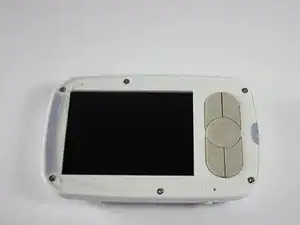
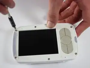
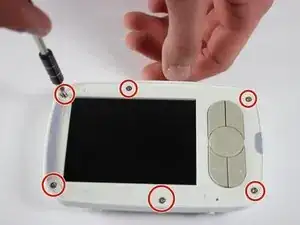
Remove the six 4mm screws using a Phillips #00 screwdriver.
-
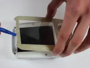
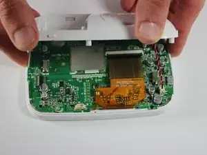
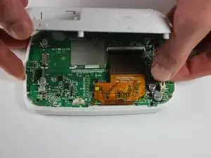
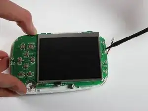
Remove the screen, exposing the circuit board.
-
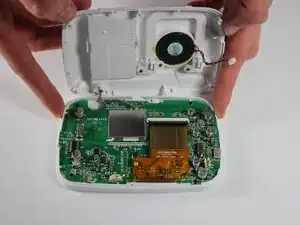
Turn device over to expose rear circuit board.
-
-
-
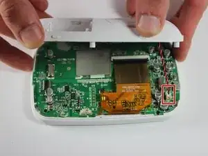
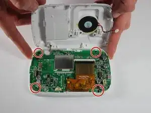
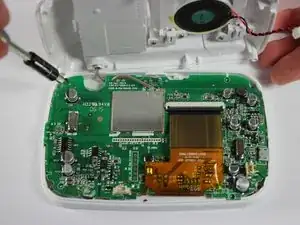
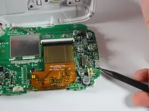
Unscrew the four 3 mm screws holding the motherboard to the unit using a Phillips #00 screwdriver.
-
-
-
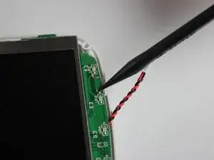
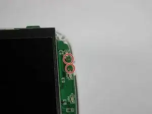
Remove the old charging port and solder the new one in place.
-
After removing the old port make sure to clean ALL the excess solder from the though holes.
-
Add a little solder to each of the 5 surface mount pads on the PCB before putting the new port on. Its a bit of a tight fit between the screen and the port so getting an iron and solder positioned correctly without blobbing or bridging is hard.
-
Place the new port on and make sure the large pins fit though the holes (the won't go all the way though)
-
Solder one of the though holes to start (if you mess up the surface pads its easier to get back off if you only have to melt one structural connection)
-
Solder the 5 surface mount pads. If the port didn't sit all the way down to the PCB you can push each pin down with the iron onto the pad and into the solder. (pre adding solder to those pads helps with this)
-
Finishing soldering the though hole pins.
-

To reassemble your device, follow these instructions in reverse order.
3 comentários
I appreciate you posting this. What kind of new charging port did you use (USB type, size, etc) and does IFIXIT sell them?
The part you are looking for is a female Micro USB B-Type solder socket. I no longer have the unit available to confirm, but I'll bet you could contact Infant Optics and confirm with them. Sorry I can't be of more help!
Worth pointing out that this guide shows an older version of the DXR-8 (2014 printed on the PCB) where the microUSB port uses through-hole leads to connect to the board. Mine is a few years newer and the port was surface-mounted, which requires more skill and care to replace. I ended up ordering the part myself and taking it to a repair shop for them to do the soldering.
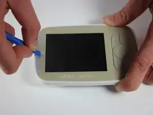
There's a layer of adhesive between the screen protector and the white plastic behind it.
Jared Astillero -
The cover is glued on. So you’ll nee d quite a bit of force to bend it up. But then it’ll come lose glue point by glue point. At first I was afraid that I’ll break it.
Marcos -