Introdução

This repair guide was authored by the iFixit staff and hasn’t been endorsed by Google. Learn more about our repair guides here.

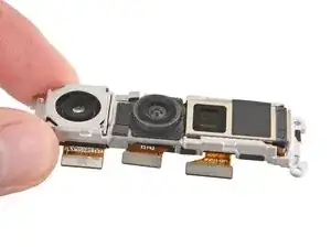
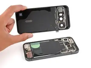
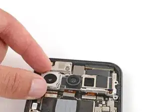
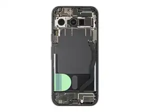
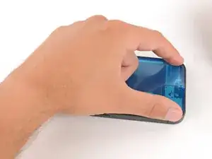
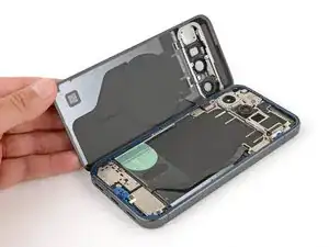
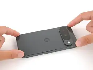
Follow this guide to replace the rear cameras in your Google Pixel 10.

If your rear camera images looks fuzzy or blurry, or if the cameras have stopped working entirely, it may be time to replace them.

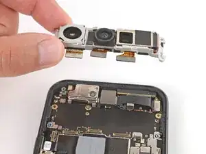
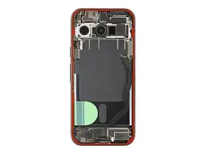
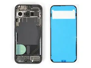
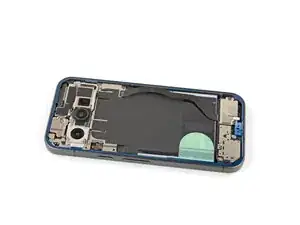
The three rear cameras (wide, ultrawide, and telephoto) come together as one assembly—to replace one, you'll have to replace all of them.

Note: Any repair can compromise the water resistance of your phone. Retaining water resistance after the repair depends on how accurately the new adhesives are applied and how clean the surfaces are.

  1. KfF631MWyOVITN1h
    KfF631MWyOVITN1h
    hZHiOHQ3mCjSMlFY
    • Let your Pixel's battery drain below 25% before starting this repair. A charged lithium‑ion battery may catch fire if damaged.

    • Unplug all cables and completely power down your phone.

  2. ZNXPUEtFRKbvLN53
    ZNXPUEtFRKbvLN53
    bIUoEdobn22IoVVJ
    lp2IWQ6SPMwIlNGV
    • Glass shards can complicate disassembly—or worse, cause injury. If your phone's back glass is cracked, follow this step.

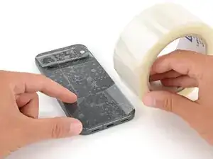
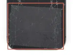
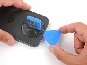
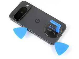
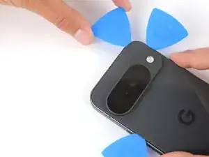
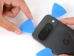
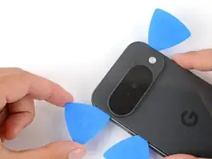
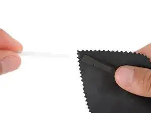
    • Apply strips of packing tape to the cracked glass until it's completely covered—this will help keep the glass contained and allow the suction cup to stick.

    • Make sure there's a single strip (not overlapping) of tape across the bottom edge, big enough for a suction cup to fit on.

    • Only cover the glass itself—don't stick any tape to the frame.

    • Consider wearing safety glasses to protect your eyes from any glass shaken free during the repair.

  3. Eor1433CTheLSBZu
    • Adhesive secures the back glass to the frame. Heating the glass softens the adhesive, making it easier to separate.

    • Heat an iOpener and lay it on the bottom edge of the back glass for two minutes.

    • Alternatively, you can use a hair dryer or heat gun to heat the back glass.

    • Improper use of a heat gun can destroy the display and/or battery—follow the linked instructions carefully.

  4. oLOKuCYcPeWQ2HGJ
    oLOKuCYcPeWQ2HGJ
    Ef2Ow1P1cZeQqOHX
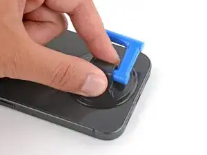
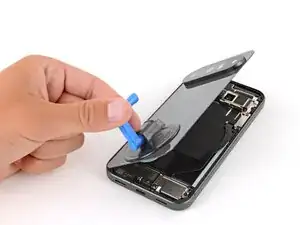
    • Apply a suction handle to the center of the back glass's bottom edge, as close to the edge as possible.

  5. qfQgMUNTkDvCKkEB
    qfQgMUNTkDvCKkEB
    6Vk1HxfKOk35NVfT
    fYFvvubfr5ObFtFc
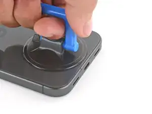
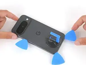
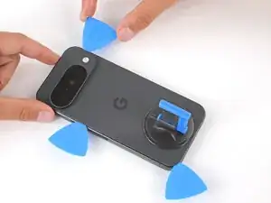
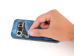
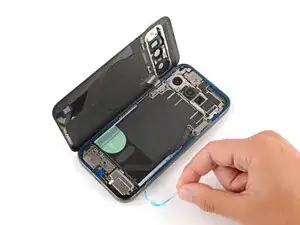
    • Pull up on the suction handle with strong, steady force until a gap forms between the back glass and frame.

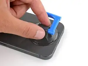
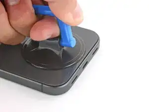
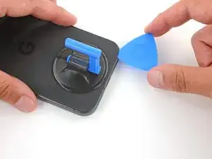
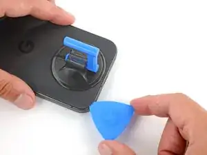
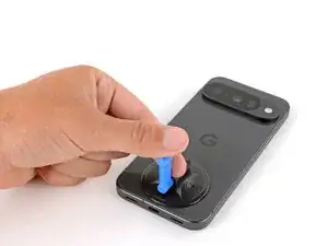
    • Insert the tip of an opening pick into the gap.

  6. hDJ6JJy1uCodprqR
    hDJ6JJy1uCodprqR
    2IaZeVuRVgkVqkqC
    XUWBcNHyy1KaCTjg
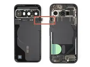
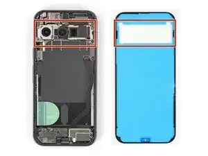
    • The back glass is secured with adhesive around the perimeter of the frame. Use this picture as a reference while you separate the adhesive.

    • A cable connects the back glass near the power button. Don't insert your pick here to avoid damaging the cable.

  7. xOxQKvfXJZbTsSvL
    xOxQKvfXJZbTsSvL
    mS5KC1TZUx5HoLNa
    2dvDqK3qdAVjqCRN
    • If the back glass feels stuck at any point when separating the adhesive, apply heat to the area and try again.

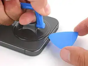
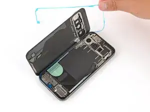
    • Slide the opening pick along the bottom edge to separate the adhesive.

    • Leave the pick inserted under the bottom left corner to prevent the adhesive from re‑sealing.

  8. kqEtcokQfPmuDLHi
    kqEtcokQfPmuDLHi
    OfoPwYwYZO6OUAlL
    AdDZbSgrOrhmS2QU
    • Insert a second pick under the bottom left corner and slide it up the left edge, stopping at the power button.

    • Leave the pick inserted to prevent the adhesive from re‑sealing.

  9. lQBDVDcom6xFHpZy
    lQBDVDcom6xFHpZy
    5BJPUUEVNFjTpc12
    gnLxKX5ChyWOEjjV
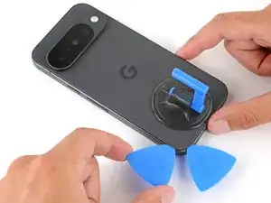
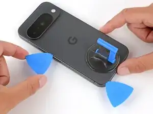
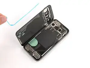
    • Insert a third pick under the bottom right corner of the back glass and slide it up the right edge.

    • Leave the pick inserted under the top right corner.

  10. paYcth1wkKEWk6Zr
    paYcth1wkKEWk6Zr
    TT4CTACoKJTfk4oH
    yeL1BLssphGKgnAk
    • Insert a fourth pick under the top right corner.

    • Slide the pick along the top edge and slightly around the top left corner, stopping at the bottom of the camera bump.

    • Don't try to fully remove the back glass yet, as it's still connected by a ribbon cable.

  11. wMT3uUDOYbIkFs4d
    wMT3uUDOYbIkFs4d
    LDDD5nFlvBMBQqKr
    3xCjVrwU5SQKkJ6x
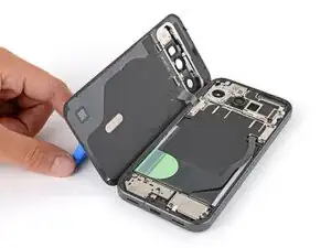
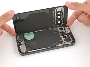
    • Flip the back glass over the left side of the phone and use the suction handle (or a sturdy object) to prop it up.

    • If the back glass still feels stuck, go back around the perimeter with an opening pick and separate any remaining adhesive.

  12. pXyW3R1HQenQpcKX
    pXyW3R1HQenQpcKX
    KeQ1TpGaobQmR5Uw
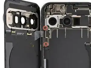
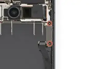
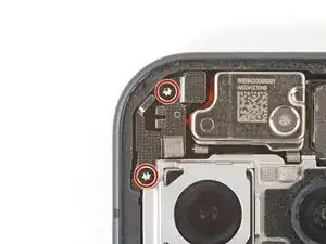
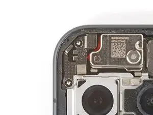
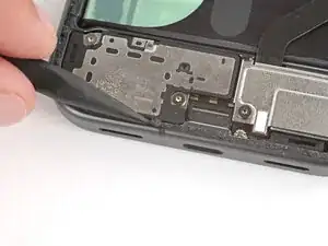
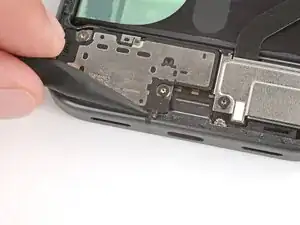
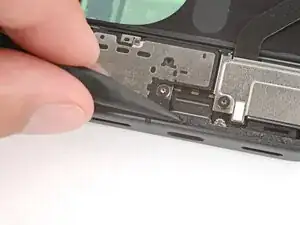
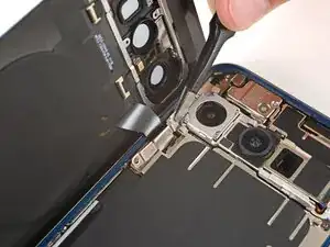
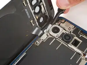
    • Use a Torx Plus 3IP screwdriver to remove the two 5.0 mm‑long screws securing the back glass connector bracket.

  13. OWKP1oRMVWYVg32L
    OWKP1oRMVWYVg32L
    X1VuJWPmCfT6LgnA
    tAMVnSyKodhx5Ocm
    • Use tweezers or your fingers to remove the bracket.

    • Be careful not to scratch or smudge the rear cameras.

  14. tJwuaNQWvPMDqVFf
    tJwuaNQWvPMDqVFf
    5MiX5cInZHTI5eje
    • Use the point of a spudger to pry up and disconnect the back glass press connector.

  15. bxHVwHGs3Fg1QPcN
    • Remove the back glass.

  16. ZVWXUcoEnJNQNNrE
    ZVWXUcoEnJNQNNrE
    2WbJcWjqXRwAMQAM
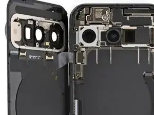
    • Use a Torx Plus 3IP screwdriver to remove the two 5.0 mm‑long screws securing the motherboard cover.

  17. sqF6vHD3krIYRsGW
    sqF6vHD3krIYRsGW
    dHXCWdvoPI2u5ML6
    q6Ck6MkFgalPk2uA
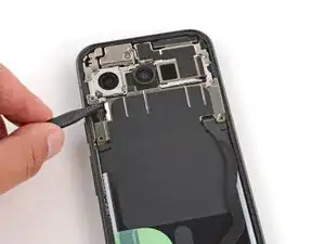
    • Use a spudger to lift the motherboard cover and gently flip it towards the bottom of the phone.

    • Be careful not to damage the delicate graphite sheet that connects the cover.

  18. ckPqJlwJSSQBlltT
    ckPqJlwJSSQBlltT
    6daYTPJ6mBmYtcVX
    • Use the point of a spudger to pry up and disconnect the battery press connector.

  19. bTCcQlLdKpIJ3UuR
    bTCcQlLdKpIJ3UuR
    RXJTXsTTpem1rZcn
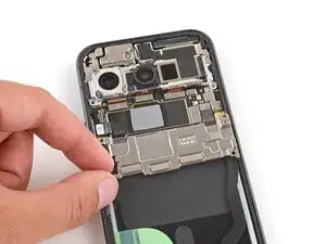
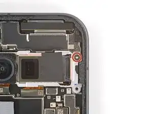
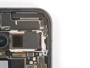
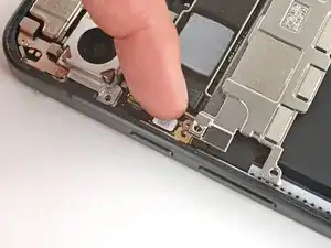
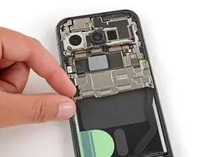
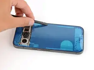
    • Use a Torx Plus 3IP screwdriver to remove the 5.0 mm‑long screw securing the front camera bracket.

  20. xGWAaJHyCIaURoQ5
    xGWAaJHyCIaURoQ5
    DNXfTTJtxSutVYr3
    PNAyyxdbQBSdsMO2
    • Use the point of a spudger to push the front camera bracket's clip in and up to release it.

    • Remove the bracket.

  21. 14PEMcNsYhCajmXp
    14PEMcNsYhCajmXp
    3AKpWIWIHOqnhqQI
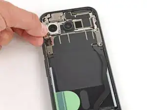
    • Use a Torx Plus 3IP screwdriver to remove the two 5.0 mm‑long screws securing the mic cover.

  22. UNGN2TTscdYn2oUY
    UNGN2TTscdYn2oUY
    CedgxvYFqXBEi3TZ
    • Remove the mic cover.

  23. sQsyAgXAyVSy4hNs
    sQsyAgXAyVSy4hNs
    vHjQjpyRlAxnZXnE
    ORMXpptS6JTFdRfx
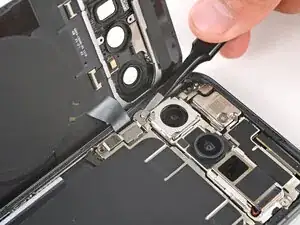
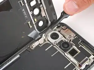
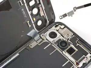
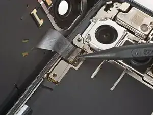
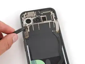
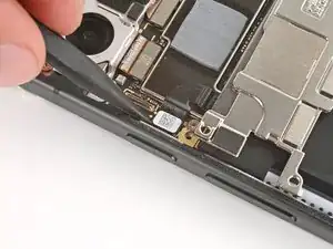
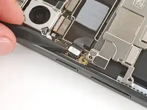
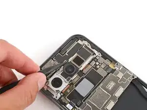
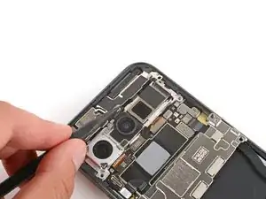
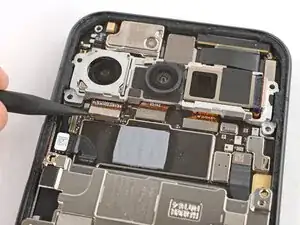
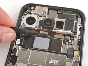
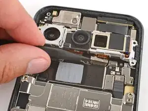
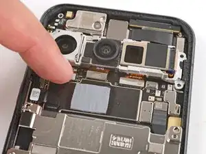
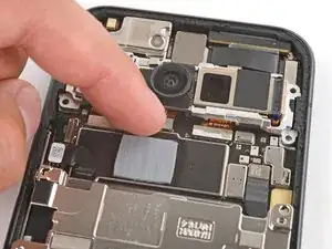
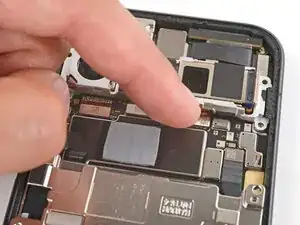
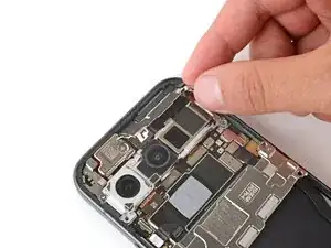
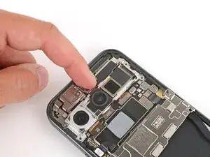
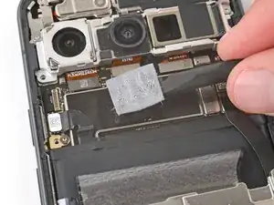
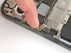
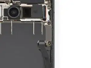
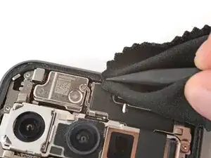
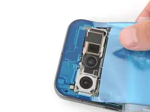
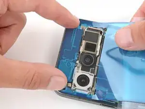
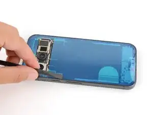
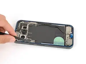
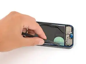
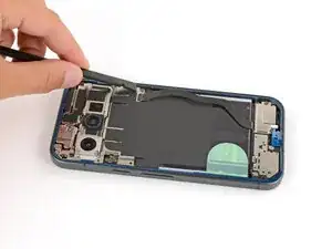
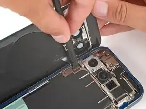
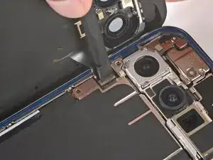
    • Use the point of a spudger to pry up and disconnect the three rear camera press connectors.

  24. Ed5JCPsLivGG5X1M
    Ed5JCPsLivGG5X1M
    dyHsZW4PyfSPJ24m
    • Remove the rear cameras.

  25. MLUuPcWD6VusMhTU
    • Congratulations on completing disassembly! The remaining steps will show how to reassemble your phone.

  26. MCE5EQMayn4VPEUr
    MCE5EQMayn4VPEUr
    oL2iundWAaSKCDsC
    • Place the rear cameras onto the motherboard.

  27. b24RMRynZuGlYcco
    b24RMRynZuGlYcco
    GiECrukqLrpQcMSy
    RWLZEpysSiPcXuU2
    • Use your finger to press down and connect the three rear camera press connectors.

  28. np5LJIUQXIKTgprm
    np5LJIUQXIKTgprm
    EtkILTNUMNMt6DrN
    • Put the mic cover back in place near the top left corner.

  29. ljyq2IEmbXgG5CiE
    ljyq2IEmbXgG5CiE
    CcDj2IZFOQstiXVe
    • Use a Torx Plus 3IP screwdriver to install the two 5.0 mm‑long screws securing the mic cover.

  30. UqSpwqCNliSJYyoJ
    UqSpwqCNliSJYyoJ
    qNSSDyThZaCbPHOs
    AeDCYncZEanEcTVV
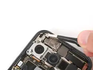
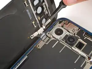
    • Slide the top corners of the front camera bracket under the lip in the frame and press the clip in to secure it.

    • Be careful not to touch the rear cameras.

  31. 2ZGRvxqufVYqZIFS
    2ZGRvxqufVYqZIFS
    JYpBc1GPqJXKSlKJ
    lFTlwdkOROSF3EVo
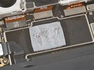
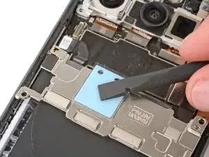
    • Check the condition of the motherboard thermal pad—it'll either be on the bottom edge of the board or on the underside of the cover.

    • If the thermal pad is damaged, follow the next two steps to replace it. Otherwise, skip down two steps.

    • Be careful when working on the motherboard cover in the next two steps, as it's still connected by delicate graphite film. If you damage the film, you'll need to replace it with a new one.

    • Use the flat end of a spudger to gently scrape up and remove all the old thermal pad from the board and cover.

    • Use high‑concentration (>90%) isopropyl alcohol and a coffee filter (or lint‑free cloth) to clean up any thermal pad residue from the board and cover.

    • Allow the alcohol to dry completely before continuing.

  32. hhJ6WXEBIrKWbaeP
    hhJ6WXEBIrKWbaeP
    MmglbxWQGc1mFbgF
    dhYcNexoMGOFP5Jf
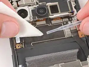
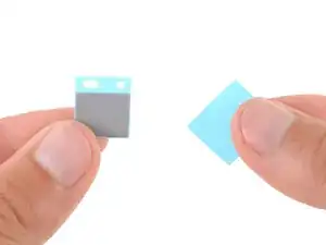
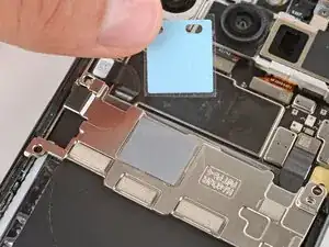
    • Remove the larger liner (without cutouts) from the thermal pad.

    • Lay the thermal pad in its square cutout on the underside of the motherboard cover.

    • Press down firmly on the entire surface of the pad with your finger or the flat end of a spudger.

    • Slowly peel up the remaining liner.

    • If the pad starts to peel up with the liner, press it back into place and try again.

  33. rjegcSJQYbOASZGf
    rjegcSJQYbOASZGf
    F1QfBDgIxVHfRVXL
    • Use your finger to press down and connect the battery press connector.

  34. lp4AG2HlkXLPhRad
    lp4AG2HlkXLPhRad
    Sl5xwOHIkKoYyIwE
    • Gently flip the motherboard cover up and back into place.

  35. gxeUiM13YEFyUSsT
    gxeUiM13YEFyUSsT
    GmaPFZ6g4YJfFWDI
    • Use a Torx Plus 3IP screwdriver to install the two 5.0 mm‑long screws securing the motherboard cover.

  36. QXJZRkNI3g2qXbnT
    QXJZRkNI3g2qXbnT
    14SYAHLMlaJxIykH
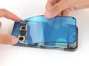
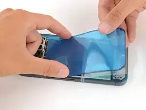
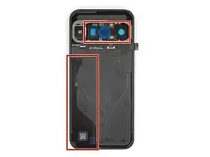
    • Before installing new adhesive, all the old adhesive and its residue must be completely removed from the frame.

    • Take your time during the next two steps. A clean frame allows replacement adhesive to lay totally flat, ensuring a better seal for your back glass.

  37. VMMJYKQFNrcKALhK
    VMMJYKQFNrcKALhK
    BAJILyWBpG23kBNT
    fG4WMgNxNxsEhMlu
    • Removing all the old adhesive can be very tricky and time‑consuming.

    • When removing the back glass adhesive during this step, be very careful not to damage the battery or any of the fragile components near the perimeter of the frame.

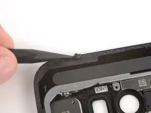
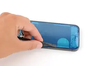
    • Use the point of a spudger to remove all the old screen adhesive from the frame. Try to "roll" the adhesive onto itself so it balls up, making it easier to remove.

    • If you're having trouble removing smaller chunks, apply a single drop of high‑concentration (>90%) isopropyl alcohol and scrape them up with your spudger.

  38. ru313xNJ4RgBrVYv
    ru313xNJ4RgBrVYv
    UdNuZmV2mOmHlGnM
    • Wrap a microfiber or lint‑free cloth around a spudger and apply a single drop of high‑concentration (>90%) isopropyl alcohol to the end.

    • Use the spudger to clean up all the remaining adhesive residue from the frame, applying more drops of alcohol as necessary.

    • Let the alcohol dry completely before continuing.

  39. UFSKA1GrWTJ61tRU
    UFSKA1GrWTJ61tRU
    CkHMrAaTb41hLL2M
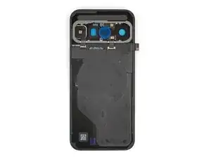
    • If you're reinstalling your original back glass, repeat the procedures in the previous two steps on the back glass to clean it.

  40. qraoed2vDyCR4gdN
    qraoed2vDyCR4gdN
    1KDNnI1FdnoXyMhq
    • Before applying the back glass adhesive, make sure you know how it will sit on the frame. If you apply the adhesive incorrectly, you'll need to restart with new adhesive.

    • Hold the adhesive above the frame to find its orientation. Use the rear camera cutout in the liner to help visualize how it will lay in the frame.

  41. NSm3nl5RM3Bn1UmH
    • Peel down the top half of the large, clear liner to expose the adhesive—don't fully remove the liner yet.

  42. pWMkpjXalCisNTYt
    pWMkpjXalCisNTYt
    mKbHE65ZDNBHFBoO
    rxdGf53IwrDPQjq3
    • Take your time aligning the adhesive with the frame—it's very sticky and can't be moved after you apply it.

    • With the larger, clear liner folded towards the bottom of the phone, lay the exposed top edge of the adhesive onto the frame.

    • Use the lip of the frame to help align the adhesive.

    • Once the top edge is properly aligned, gently press down on the top corners to secure the adhesive.

  43. lZDGLEHaYmxot4N4
    lZDGLEHaYmxot4N4
    oHrNSUfaojet6TRU
    tJJYoFeEWtuKq3CR
    • Slowly lay the rest of the adhesive onto the frame, pressing it into place and peeling away the larger liner as you go.

  44. QAwDhU4OQ5BeHKXt
    QAwDhU4OQ5BeHKXt
    FLFPfAklXVMlpJDT
    iIMcTYnMqNpAnJXV
    • Use a spudger to press down firmly on the adhesive to secure it to the frame.

  45. oid4MKvTflgkZQBP
    oid4MKvTflgkZQBP
    wd25VHTslLgCG2LJ
    qO3pth2ZG3kno6G6
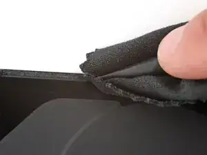
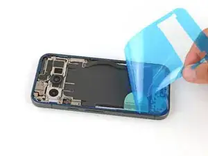
    • Slowly peel up and remove the large colored liner, gripping it from the cutout near the top edge.

    • If the adhesive starts to peel up with the liner, check that you’ve pushed all of it into place with your spudger. If it continues to peel up, hold it down with the point of your spudger as you go.

  46. 4cTIC1B5YRcTwlXI
    4cTIC1B5YRcTwlXI
    OPZplJBKBd6UXWbZ
    Tw4VNRZfJHN15fE6
    • Use a spudger to press down firmly on the adhesive to secure it to the frame.

  47. EDcPxkQoukr3hLXG
    EDcPxkQoukr3hLXG
    KkpeQAAWCj5WKiEG
    • If you're installing a new back glass, your replacement will have various protective liners and pieces of tape on the underside that must be removed. Your part may have different pieces in different locations, so make sure to check carefully!

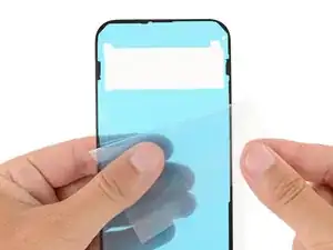
    • Remove all liners from the underside of the back glass, paying special attention to the front camera cutouts and bottom edge.

    • Usually, you can identify the liners by their pull tabs.

  48. onLrSEIM12vQMwC3
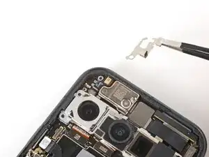
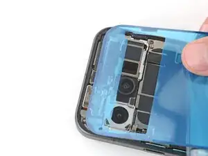
    • Apply a suction handle to the back glass and prop it up on the left side of your phone, so the cable is near its connector.

    • Alternatively, you can use a sturdy object (such as a stack of books) to prop up the back glass.

  49. cTmfjEOB4rGB5CW2
    cTmfjEOB4rGB5CW2
    jGIHjdRKqbEXGOCO
    • Use the flat end of a spudger to connect the back glass press connector to its socket.

    • This can be tricky, as there's very little play in the cable. Move the back glass as necessary to help, and don't try to force the connector into place—reposition it and try again.

  50. PnEuIVtq62mxnC2y
    PnEuIVtq62mxnC2y
    aVkckcbfHFuEkCAA
    WeGMCbJKg1ttVTPf
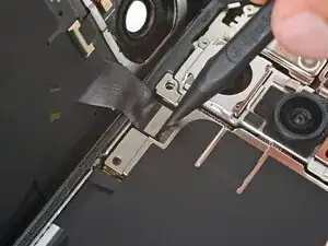
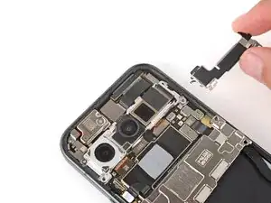
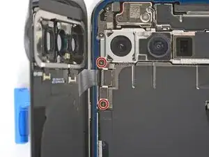
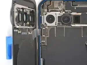
    • Put the cable's bracket back in place, making sure the tab on the right edge goes under its groove.

  51. XS2EkHpdsIClu5sR
    XS2EkHpdsIClu5sR
    CvXFUrgFMYjOKEvS
    • Use a Torx Plus 3IP screwdriver to install the two 5.0 mm‑long screws securing the bracket.

    • This is a good point to power on your device and test all functions before sealing it up. If you have trouble, try some basic troubleshooting. Be sure to power back down completely before you continue working.

  52. Mg4S4FoNyqNEKKJi
    Mg4S4FoNyqNEKKJi
    dQHboLRdrSAXPYDT
    5WB5NOBbcvpBmJdy
    • Remove the remaining liners from the back glass adhesive.

    • If the adhesive starts to peel up with the liner, check that you’ve pushed all of it into place with your spudger. If it continues to peel up, hold it down with the point of your spudger as you go.

  53. JTyIDehsCsAKJdYx
    JTyIDehsCsAKJdYx
    SwfeSr2SB5KsyqXf
    ZLJnI3iDKXN2uwmi
    • Flip the back glass onto the frame and press it firmly into place.

    • Hold your phone up and squeeze firmly around the perimeter to strengthen the bond.

    • For an even stronger bond, you can stack books on the back glass or use screen vise clamps.

Conclusão

Congratulations on completing your repair!

To run a diagnostics test with the built-in Pixel Diagnostic tool, click here.

Take your e-waste to an R2 or e-Stewards certified recycler.

Repair didn’t go as planned? Try some basic troubleshooting, or ask our Answers community for help.

Spencer Day

Membro desde: 14/09/22

165254 Reputação

0 comentários