Introdução

Congratulations on getting the Framework Laptop 16 DIY Edition! Follow this quick start guide to assemble your laptop and get it running.

  1. jjWXSOKSyMfG4lT3
    jjWXSOKSyMfG4lT3
    PAdAjYaSaKUdgqPj
    • Unbox your Framework Laptop and make sure you've received the following items:

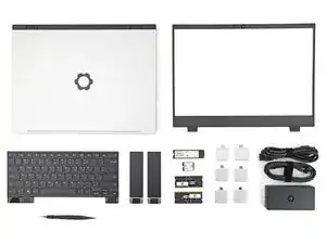
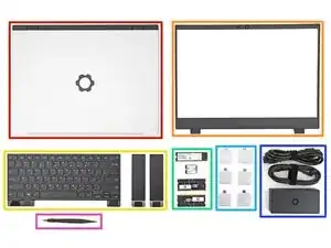
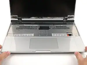
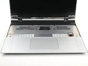
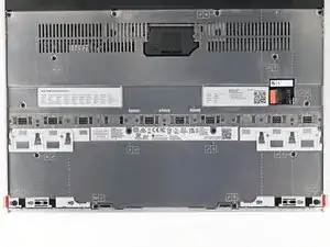
    • Framework Laptop chassis with pre-installed Mid Plate, Touchpad Module, and Touch Spacers.

    • Bezel

    • Keyboard and Input Modules

    • Memory and Storage

    • Expansion Cards

    • Power Adapter

    • Framework Screwdriver

  2. 5DaiJysNhBkNE6QV
    5DaiJysNhBkNE6QV
    hVfduBcKwXB4Xd2j
    • Open the laptop.

  3. qADGiGQXgXaaArmy
    qADGiGQXgXaaArmy
    rUfWrE1mtBDPyOmG
    • Remove the plastic cover.

    • The protective cover is made of post-consumer recycled PET and is highly recyclable. Please recycle this with your household recycling.

  4. TaHbq5mEbSvNKtXU
    TaHbq5mEbSvNKtXU
    cG36MPTGLIqREId2
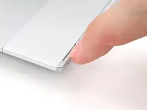
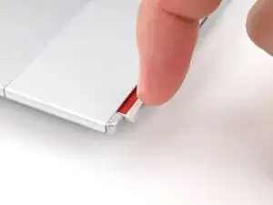
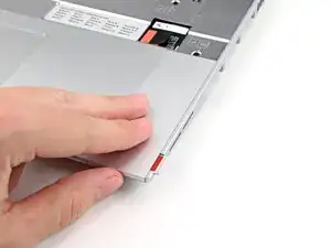
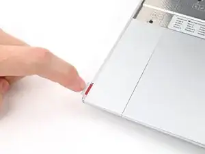
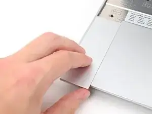
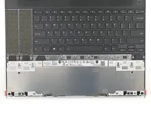
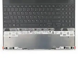
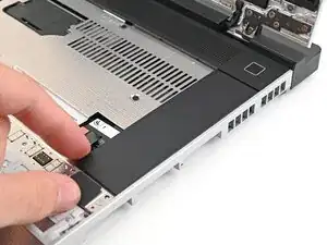
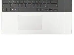
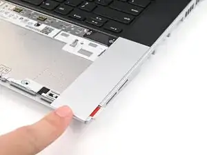
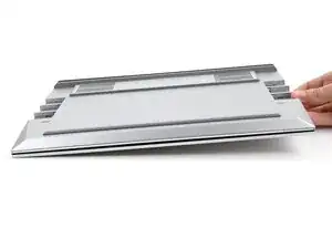
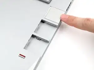
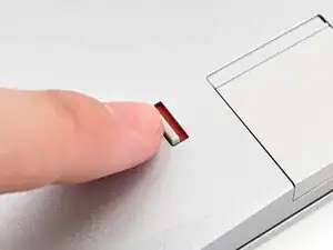
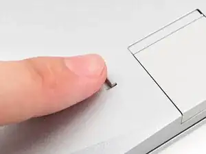
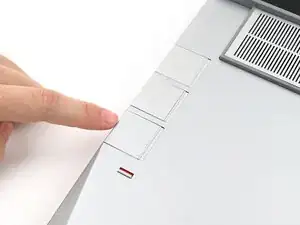
    • Use your fingernail to pull out the Input Module latch and unlock the Touchpad Spacer next to it.

  5. FA5rjIurxQmxBsTZ
    FA5rjIurxQmxBsTZ
    L1eXiI2WxckC5xjU
    55ciBapNeuqHFerv
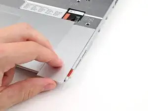
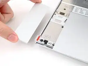
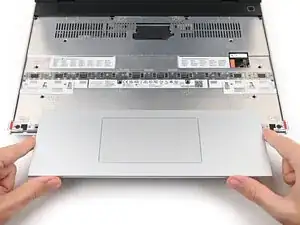
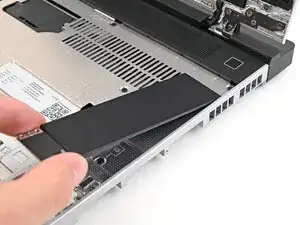
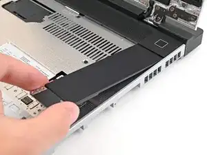
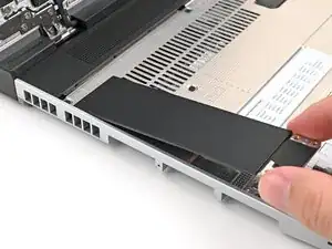
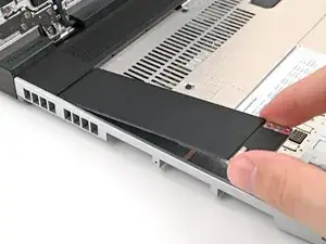
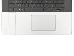
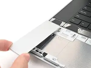
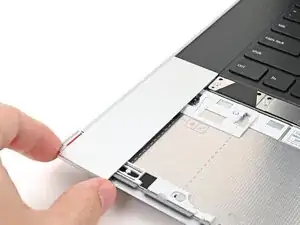
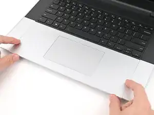
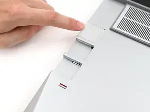
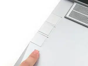
    • Use your fingers to slide the Touchpad Spacer toward the bottom edge of the laptop and unclip it.

    • If you're having trouble, check if the corresponding Input Module latch is properly unlocked.

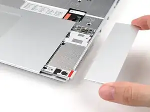
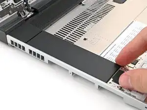
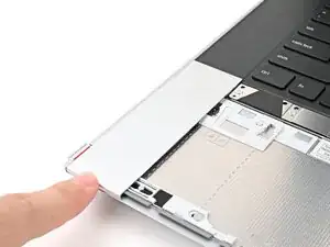
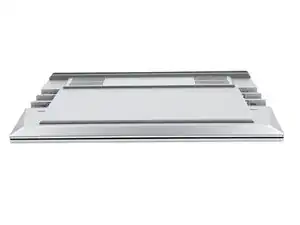
    • Lift the Touchpad Spacer off the laptop and remove it.

  6. fT5aYgnXKyRdJwVn
    fT5aYgnXKyRdJwVn
    q2bjcjliL5oSRcMk
    hTJuY3PwyQDQXc2n
    • Repeat the previous two steps to remove the other Touchpad Spacer.

  7. yDcxoQ3kmeWj5Fvf
    yDcxoQ3kmeWj5Fvf
    VNeih2ccZce43IHm
    YdWIi3qvaDfCfRyC
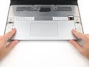
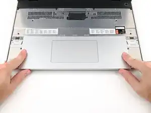
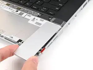
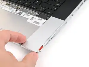
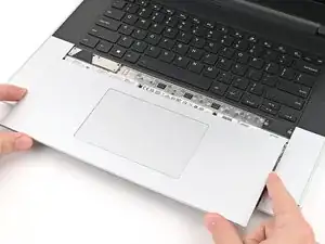
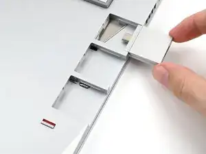
    • Use your fingers to slide the Touchpad Module toward the bottom edge of the laptop and disconnect it.

    • Lift the Touchpad Module and remove it.

  8. EfUhRDiDFIYqtFbt
    EfUhRDiDFIYqtFbt
    SBCYQjRtWB63dAUS
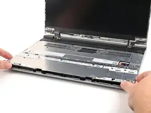
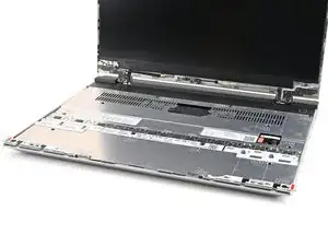
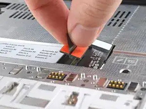
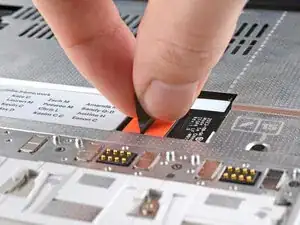
    • Grip the black pull tab on the Mid Plate cable press connector and lift up to disconnect it.

  9. 5feuEeJq6QGJDBdS
    5feuEeJq6QGJDBdS
    lHH1pWvBIjjgoBNS
    • The Mid Plate screws are ordered from 2–17 (number 1 is the press connector). You don't have to follow the order, but you can use it to help keep track of the screws you've loosened.

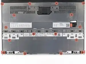
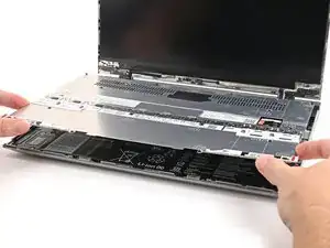
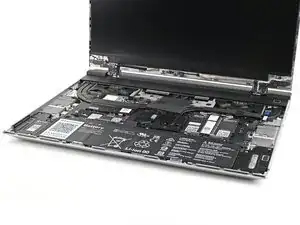
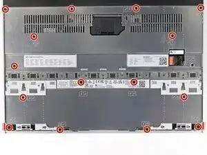
    • Use your Framework Screwdriver to loosen the 16 captive T5 Torx screws securing the Mid Plate.

  10. HvLOCwtKSQBybyKA
    HvLOCwtKSQBybyKA
    mwQa5YOUCDKhBYRA
    lZAZqcsp2XaAKHon
    • Use your fingers to lift the Mid Plate off the laptop and remove it.

  11. Oo4SFqcBPPEnrHKB
    Oo4SFqcBPPEnrHKB
    F1gn1FVtviG6XmPY
    PIvslxyuVT54V1MS
    • Hold the memory module by its edges. Don't touch the gold contacts with your fingers. If you do, wipe the contacts with a clean, lint-free cloth to remove any finger oils.

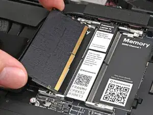
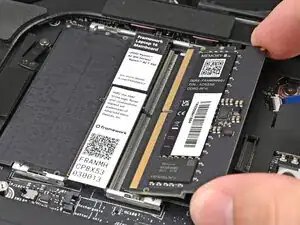
    • Orient the module with its label facing down and align the gold contacts with the left socket labeled DDR5 Channel 0.

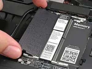
    • Insert the contact edge into the socket at a shallow angle. The gold contacts should mostly be covered by the socket.

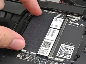
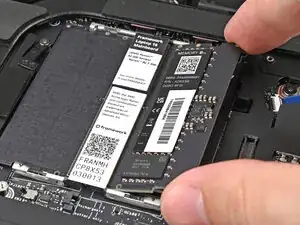
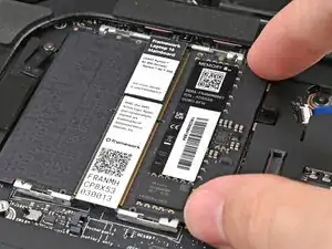
    • Press the edges of the memory module down until the side clips lock it in place.

  12. XZ2atPOnWXajVbHn
    XZ2atPOnWXajVbHn
    OnDVEmYhXpZfAZDN
    tEcc5uMpgNgQbYe5
    • If you're using two memory modules, orient the other module so its label is facing upward and repeat the previous step for the other socket labeled DDR5 Channel 1.

  13. UTJYNw2WAEgJyXJC
    UTJYNw2WAEgJyXJC
    TjdTtirU6JtpaoHp
    • If you're installing a secondary SSD, follow the next five steps. Otherwise, skip here.

    • Remove the blue liner from the secondary SSD thermal pad.

    • The thermal pad can vary in color—yours may be gray, orange, or pink.

  14. WbQFtEcvn6wXA2I3
    WbQFtEcvn6wXA2I3
    TcML6fQonhCwfCN6
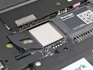
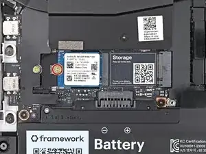
    • Use your Framework Screwdriver to remove the 2 mm‑long T5 Torx screw securing the secondary SSD.

  15. Du12D6uh6X4YMhrt
    Du12D6uh6X4YMhrt
    RbLnoRd5RgbJWMCx
    TYVEfWMMS6MJBjSX
    • Hold the SSD by its edges. Don't touch the gold contacts with your fingers. If you do, wipe the contacts with a clean, lint-free cloth to remove any finger oils.

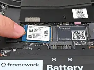
    • Align the SSD's gold contacts with its socket.

    • Insert the SSD partially into the socket at a shallow angle. You should still be able to see most of the gold contacts.

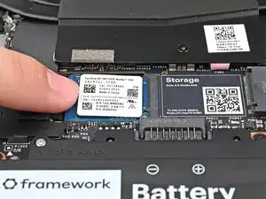
    • Press the SSD flat to the Mainboard.

  16. qJw1GhdrkOscY5SO
    qJw1GhdrkOscY5SO
    rQQwrFDhtHTZ4lJ4
    • While keeping the SSD flat to the Mainboard, use your finger to slide the SSD into its socket until its golden contacts are completely covered.

  17. iElo4r1U2PGUwp5G
    iElo4r1U2PGUwp5G
    ZQ4dPKUeStujDUjL
    • Use a Framework Screwdriver to install the 2 mm‑long T5 Torx screw securing the secondary SSD.

  18. 4bBZ4LZfBlXXZdWX
    4bBZ4LZfBlXXZdWX
    ir6HGAkSFRhDNobh
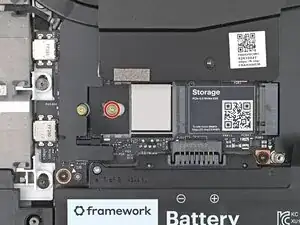
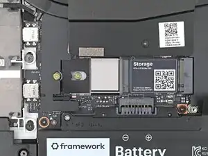
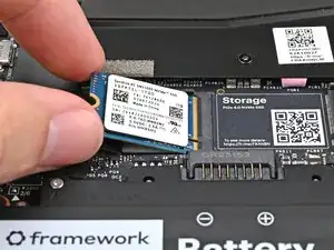
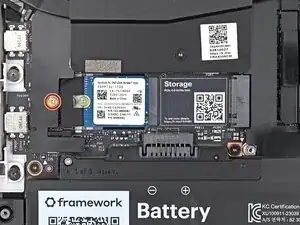
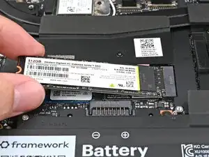
    • Use your Framework Screwdriver to remove the 2 mm‑long T5 Torx screw securing the primary SSD.

  19. MaBKRNFGEHBGcMfS
    MaBKRNFGEHBGcMfS
    FgxofLHIOsXck62M
    • Hold the SSD by its edges. Don't touch the gold contacts with your fingers. If you do, wipe the contacts with a clean, lint-free cloth to remove any finger oils.

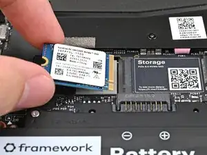
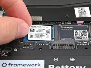
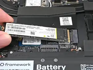
    • Insert the SSD into the socket at a shallow angle. The gold contacts should mostly be covered by the socket.

    • The SSD fits into the socket in one orientation. If it doesn't feel like it fits, try flipping the module.

  20. TQKpfHfRBVcTefWU
    TQKpfHfRBVcTefWU
    Pq1xxvALtlLYSEdO
    NY3STsyBQAPpxAln
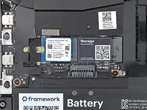
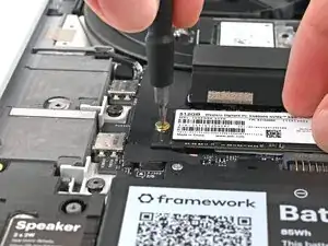
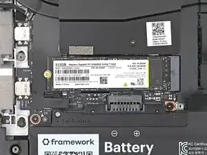
    • While holding the SSD flat to the Mainboard, use your Framework Screwdriver to install the 2 mm‑long T5 Torx screw securing the primary SSD.

  21. nrH61Uv6gJ2TRgrn
    nrH61Uv6gJ2TRgrn
    yY4uBgkaXNREYbLr
    LxfrEMhDaPMVFVgJ
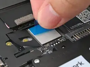
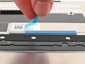
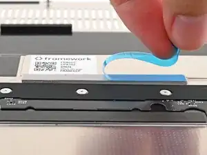
    • If there's a blue liner on the thermal pad located on the bottom of the Mid Plate, use your fingers to peel it off.

  22. gXNsc2nJPdU35ofk
    gXNsc2nJPdU35ofk
    qDNCjIuH4ZAmCvEn
    NcHAlEUhjAAVaytu
    • Place the Mid Plate on the laptop, making sure it sits evenly on its alignment pegs.

  23. voUYRnLhTKghRRZC
    voUYRnLhTKghRRZC
    ggQbItNujnAjKwNv
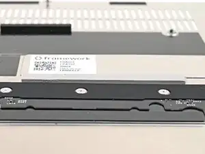
    • Use your Framework Screwdriver to tighten the 16 T5 Torx captive screws in order (starting with 2) to secure the Mid Plate evenly.

  24. 5qabXsYpR1qdiUrN
    5qabXsYpR1qdiUrN
    UaxymKGZErRi6RNQ
    • Align the Mid Plate cable press connector over its socket and press down to connect it.

  25. TWFgZrJWRhxlJUep
    TWFgZrJWRhxlJUep
    2OJMU2lnWBgKYJCr
    YJEOSfPQhoKwlmoA
    • The top row of the laptop is fully customizable, but each Input Module follows the same installation procedure. The next three steps show installing the combination used in the first photo.

    • Check out this page for all of the possible Input Module combinations.

  26. ADZopgsnuQAjCfCj
    ADZopgsnuQAjCfCj
    GkIdUPebtyEQnHmK
    1nTQIZwQFIvuEZwu
    • Hold the Input Module at a slight downward angle and align it with one of the dotted lines on the Mid Plate.

    • Slide the top lip of the Input Module underneath the ventilation plate and lay the module down flat to let the magnets pull it into place.

    • Make sure the alignment pegs are slotted into the Input Module and that it sits flat. Otherwise, pull the module off the laptop and readjust it.

  27. WWugDtk5uo3jnC3f
    WWugDtk5uo3jnC3f
    GBldSX5XfG6Hof2u
    HmGD5hcu1DOS54aM
    • Repeat the previous step for the other Input Module.

    • If you've already installed a numpad, you'll only have space for the keyboard and not another module.

  28. qvE2xFhMMZZrPHsH
    qvE2xFhMMZZrPHsH
    yX1Twt1t1SQZMcFc
    XpHHgwuKUoNHvmKk
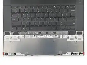
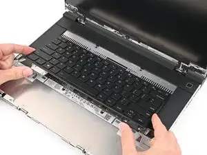
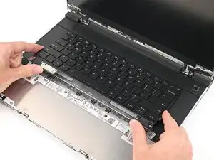
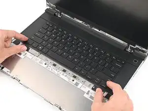
    • Hold the keyboard at a slight downward angle and align it with two of the dotted lines on the Mid Plate.

    • The keyboard can be placed on the left, center, or right edges of the laptop depending on which Input Modules you've installed.

    • Slide the top lip of the keyboard underneath the ventilation plate and lay the keyboard down flat to let the magnets pull it into place.

    • Make sure the alignment pegs are slotted into the keyboard and that it sits flat. Otherwise, pull the keyboard off the laptop and readjust it.

  29. RtK1MWGnCTCand2J
    RtK1MWGnCTCand2J
    JDxqcIbSDG5GPS2I
    uTMpk2sKpyEFuMXU
    • The bottom row of the laptop is fully customizable. The next four steps show installing the combination used in the first photo.

    • Note: for the Touchpad Module to be on the left, the keyboard can't be installed in the center.

  30. cKtuBMDTBeosv6Tm
    cKtuBMDTBeosv6Tm
    AqTPkjbBITMwXJSI
    WNK6ymIWONAHo4Rk
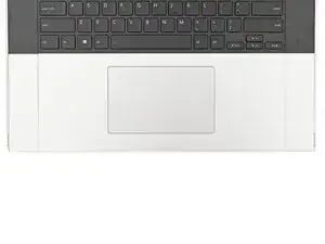
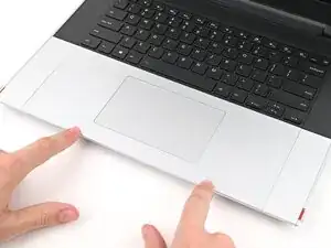
    • Place the Touchpad Spacer over its spot on the laptop with the bottom edge overhanging slightly.

    • Slide the Touchpad Spacer towards the top of the laptop to secure it.

  31. LLEEskWJyAEwTjSY
    LLEEskWJyAEwTjSY
    weCJD4CUetcjIUOW
    eOYJSnuBT5Xe1Fhw
    • Repeat the previous step for the other Touchpad Spacer.

  32. VSaCbAuhhRxgPKs4
    VSaCbAuhhRxgPKs4
    5JYALYoClCoAja3r
    IlQRUtwjFfyuElWG
    • Place the Touchpad Module flat on its cutout so its clips are properly aligned.

    • Press the Touchpad Module down and slide it into place so it lines up evenly with the bottom edge of the laptop.

  33. LOAVcAIXPs3Rh1Ih
    LOAVcAIXPs3Rh1Ih
    RZ3cThuVk1JShtPH
    mqQfDfjdSlGkOLqu
    • Push the Input Module latches back into place to lock them.

  34. InV2jSc1ZfU1eLhV
    InV2jSc1ZfU1eLhV
    oZ3fIle2gQfD6UyR
    dPTFPQ3lXAdtFNoO
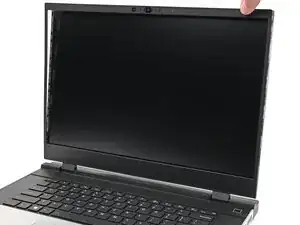
    • Align the bezel over the perimeter of the display and let the magnets pull the bezel into place.

    • The bezel should "snap" into place. If it doesn't, realign it and make sure it sits flush with the display.

  35. QXyL1G4jZCCpsO3K
    QXyL1G4jZCCpsO3K
    gAGDKbLyFahiMmgr
    • Close the laptop and flip it over.

  36. bR1NeTgdEICEUCQq
    bR1NeTgdEICEUCQq
    i5C2c2vYGEnMTmWj
    tyukoQU2xvZEg3vT
    • If you have the AMD Ryzen™ 7040 Series, click here for information on Expansion Card compatibility.

    • If you have the AMD Ryzen™ AI 300 Series, click here for information on Expansion Card compatibility.

    • Slide an Expansion Card into an Expansion Card slot.

    • You don't need to unlock the latch to install the Expansion Cards—only when you want to remove them.

    • The Expansion Cards should click into place, and the front edge should be flush with the laptop.

    • Repeat for the remaining Expansion Cards along that edge.

  37. pKluVcnCjD3Q1GoA
    pKluVcnCjD3Q1GoA
    2vKUjMaOgVOvFApC
    • If there's a red bar showing under the Expansion Card latch, use your finger to flip the latch and lock the row of Expansion Cards above it.

  38. KTbTDyvPHNx1lIAV
    KTbTDyvPHNx1lIAV
    bDWvl1qmVBxkJ3Xo
    6HQiwcAQThMMdDy3
    • Repeat the previous two steps for the other row of Expansion Cards.

  39. PgNYRjZOvmhWfMqT
    PgNYRjZOvmhWfMqT
    MD2QSwPKRSnOSJLn
    xQlqlxqGpvOUuMdi
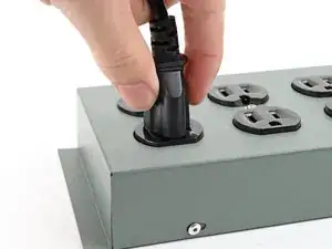
    • Plug the AC Cable into the Power Adapter.

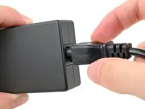
    • Plug the USB-C Cable into the Power Adapter.

    • You can plug either end of the USB-C cable into the adapter.

    • Plug the AC Cable into a power outlet.

  40. XRXROofSd1neQwrr
    • Your Framework Laptop ships in shipping mode, where the battery is disabled until you plug the laptop in for the first time.

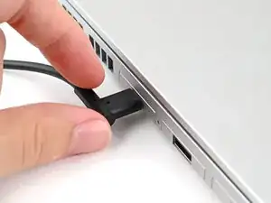
    • Plug the USB-C Cable into any USB-C port on your laptop.

  41. MwCiM3MslsRsapfn
    • You're done assembling your Framework Laptop! Now, you'll need to install an OS.

    • If you're installing Microsoft Windows, check out this guide.

    • If you're installing Linux, check this page for more details.

    • For drivers, firmware, and software updates, check out this page.

Conclusão

For drivers, firmware, and software updates, check out this page.

If you need help, contact Framework support.

Alex Diaz-Kokaisl

Membro desde: 16/01/22

227430 Reputação

0 comentários