Introdução

  1. VsbQhgexUfxSRTdB
    • Remove the SIM card tray using a SIM card ejector tool.

  2. bQ1Qo2P5UvKObfLI
    • Unscrew the two T2 Torx screws on the bottom of the phone, surrounding the charging port.

    • The screw hole is shallow and your screwdriver will slip if it is not exactly lined up. Be patient and keep your hand steady while unscrewing.

    • While the screw technically is a T2 Torx screw, a 0.7 mm Hex screwdriver may also work sometimes.

  3. tqNulEdGOSINiVt1
    tqNulEdGOSINiVt1
    QwOWWVXtTuWmJPGu
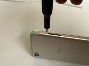
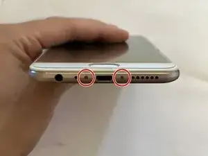
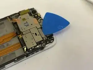
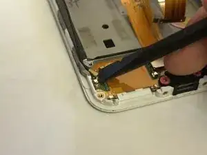
    • Insert your opening pick or similar thin opening tool into the thin gap above the audio jack.

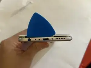
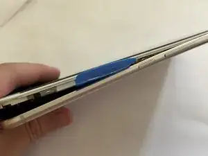
    • Force your opening pick as deep as it can. Push down on the pick to release the clips holding the housing onto the rest of the device.

  4. A2Y4AD5rNwiMK1DE
    A2Y4AD5rNwiMK1DE
    gYXHNmUuCYxfNlyF
    3tHJaXHULTxQg2pL
    • Unscrew all visible screws on the top half of the device using a PH000 Phillips head screwdriver.

    • The screw highlighted in orange is covered with a warranty sticker that must be unscrewed to proceed. This will void your warranty.

    • Peel the graphite pad off.

    • Unscrew the last Phillips head screw that was under the graphite pad.

  5. EC3mOe52JsXRE2wA
    EC3mOe52JsXRE2wA
    MxZJHLGjkOM2k2L6
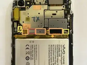
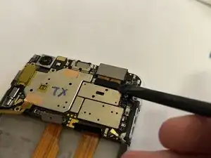
    • Remove the bracket at the bottom of the motherboard.

    • The bracket needs to be pulled out and up towards the screw holes.

    • Disconnect the battery first before disconnecting anything else.

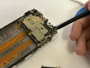
    • Disconnect the other connectors shown.

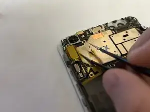
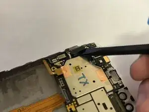
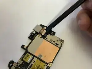
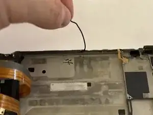
    • Disconnect the antenna wires.

  6. fptYyyiZ4IMueS25
    fptYyyiZ4IMueS25
    WERmFus2nRRy5jN3
    jKpmXKDkIbuxOHmK
    • Follow the manufacturer's guide sticker to remove the battery.

  7. xPB5HNDR4JjiSa1e
    xPB5HNDR4JjiSa1e
    SYK14FWk3IvM4y5Q
    • Remove the bracket covering the double front-facing camera module, then disconnect and remove the module itself.

    • The bracket needs to be pulled out and up towards the screw hole.

  8. mRMaQlXSYD4UDSnN
    • Remove the SIM tray bracket.

    • The orientation of this bracket matters!

  9. IJsRgit2bVtmIBxR
    IJsRgit2bVtmIBxR
    eO2pQFyGjMAbPIJw
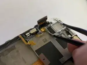
    • Carefully remove the yellow Kapton tape, then remove the bracket covering the display connector.

    • The bracket needs to be pulled out and up towards the screw hole.

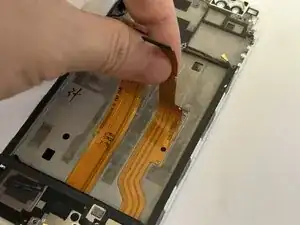
    • Disconnect and bend away the display cable.

  10. HGMZIVeANkedCs3D
    • Carefully remove the motherboard from the chassis.

  11. YNPhN6RtpDGkFqsw
    • Flip the motherboard over and remove the back-facing camera module.

  12. KXJ4ULC3CIfoxNij
    KXJ4ULC3CIfoxNij
    ZTYRSYaj1wAGeljH
    • Use extreme caution when handling the vibration motor's cable. It is extremely fragile and is stuck on with strong adhesive.

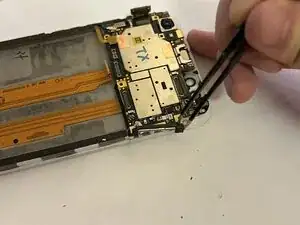
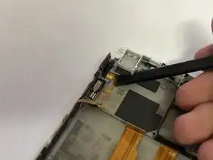
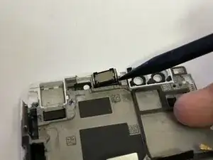
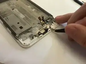
    • Use tweezers to lift the cable for the vibration motor.

    • Use a spudger to finish removing the cable and motor.

  13. EejnVm1s1p5RLLSi
    • Use the pointed end of a spudger to remove the earpiece speaker.

  14. QYHwGPxHgqTdUDqE
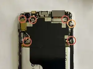
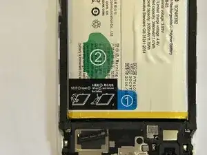
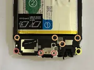
    • Remove the screws shown using a PH000 Phillips head screwdriver.

    • Screws marked with orange are hidden behind foam tape.

    • There is one screw with a warranty sticker on it. We've already voided our warranty earlier, so we unscrew it anyways.

  15. AmyvFNhCDt16RIjP
    • Remove the cover of the daughter board.

  16. LvQGQj25JVJXuPgf
    LvQGQj25JVJXuPgf
    wxLk1nRcX54HeePL
    n2FZNIqDDxXyL1hf
    • The ribbon cables are very easy to rip. Use extra caution.

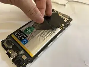
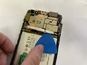
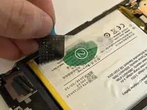
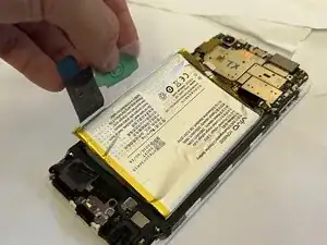
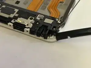
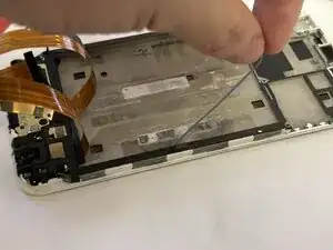
    • Peel the ribbon cables running down the middle of the device, then peel the antenna cables running down the sides of the housing.

    • Remember the colors of the antenna cable. When reassembling, the color of the cable matters.

    • The antenna cables are routed through a small channel in the chassis that is covered with foam tape. The foam tape can be peeled back for easier access when routing the antennas.

  17. JKT61gYkb5QZH3jj
    JKT61gYkb5QZH3jj
    31bKKUHm4prfkYaC
    • Use a spudger to disconnect the antennas from both sides of the daughter board.

  18. JRhJtvhnTxV3ar5x
    JRhJtvhnTxV3ar5x
    ThiphESYEDABtaIM
    VuvbJGZqUKJwgrKn
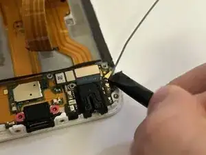
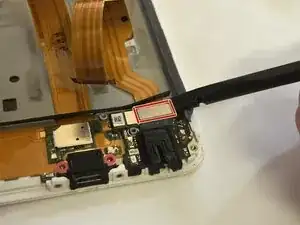
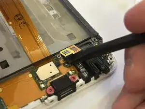
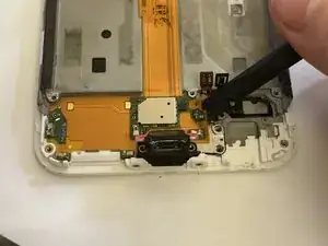
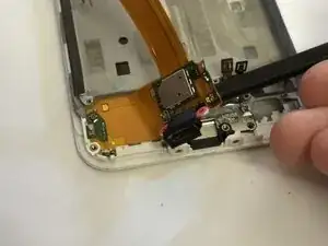
    • Using a spudger, disconnect the three connectors on the audio jack board:

    • Interpose cable

    • Daughter board display connector

    • Home button cable

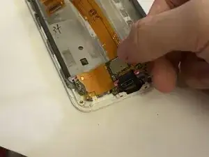
    • Afterwards, remove the audio jack board.

  19. ybaEbUriENLMYAZM
    ybaEbUriENLMYAZM
    GobaDlMW5dNsJYyc
    bN1PTkODCHJXktgl
    • Peel away the charging port.

  20. NVPO5GJbl6XnH53I
    NVPO5GJbl6XnH53I
    jD4KoNVg4jfLUJWJ
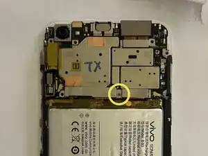
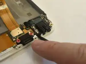
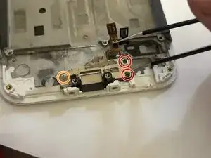
    • Remove the two screws exposed by the removal of the audio jack.

    • There is another screw (marked with orange) that for this bracket that may be hidden underneath residue graphite tape. Ensure you have removed this screw or else you will damage the bracket when removing it.

  21. b6eaawteEKjIUrPK
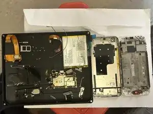
    • There it is! The teardown is now complete. Opening the device was a bit tricky, but the insides are really easy to work with if you're careful.

Camuise

Membro desde: 23/11/18

1664 Reputação

0 comentários