Introdução
-
-
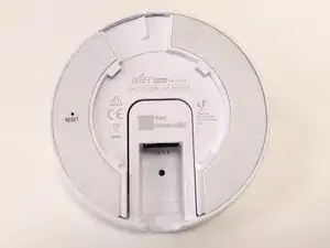
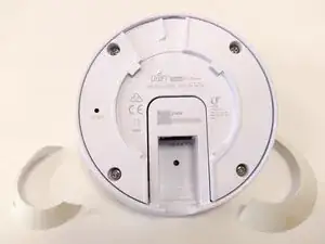
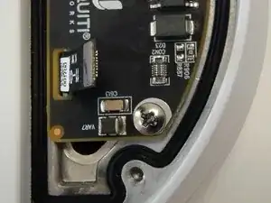
Remove the two rubber adhesive strips to uncover the four screw holes
-
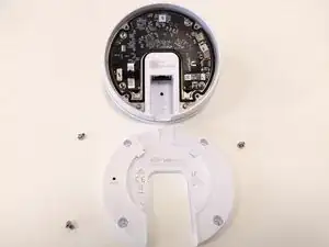
Remove the four small screws and lift the cover.
-
-
-
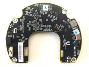
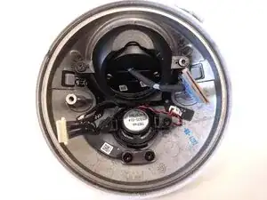
The main board is now visible.
-
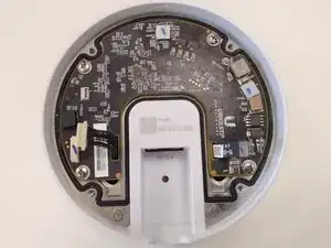
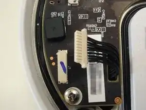
Remove the four screws
-
Unplug the two highlighed connectors
-
First connector, on the left in the picture, for the leds, microphone, speaker
-
Second connector, on the right in the picture, for the ethernet port
-
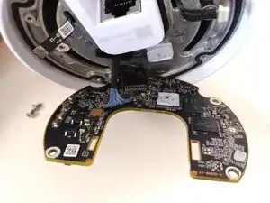
You can now gently lift the main board, passing the two cables that you unplugged through their respective holes on the board. There will be a bit of resistance as there is a chip with thermal paste that adheres to the underlying metal cover
-
-
-
Remove the cable connected to the bottom of the main board
-
This cable is connected to the camera
-
-
-
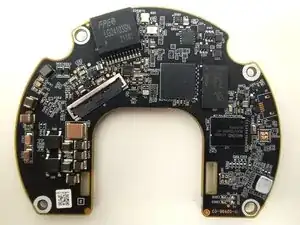
You can now remove the main board
-
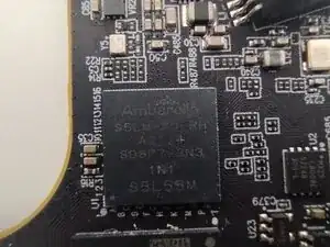
I cleaned the chip from the thermal paste to reveal that it is an Ambarella S5L IP Camera SoC (full code: Ambarella S5LM-A0-RH A2114 SD8P7-2N3 1N1 S5L55M)
-
-
-
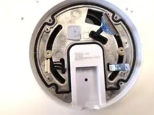
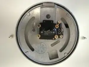
Remove the two screws on the sides of the rotating disc
-
You can now remove the rotating disc that includes the ethernet connector (here pictured from below)
-
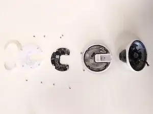
You have now access to the main body with the camera, the microphone, the speakers and the leds
-