Introdução
This particular camera stopped working for me, so I decided to take it apart.
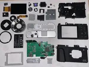
This is not a logical way to take apart this device. I plan to make some repair guides for this model in the future.
-
-
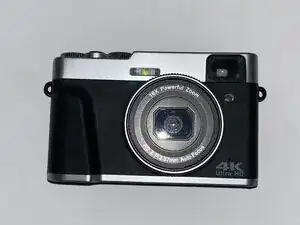
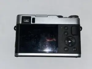
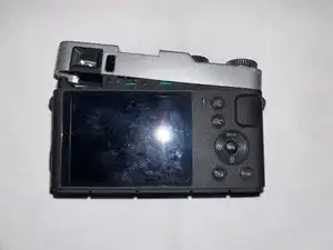
Here, I've got my hands on a camera that no longer works.
-
Seeing that I can't use it for anything useful, I decided to take it apart, because why not?
-
-
-
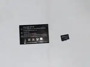
This camera came with two 3.7V 800mAh NP-60 li-pos and a generic 32GB microSD card.
-
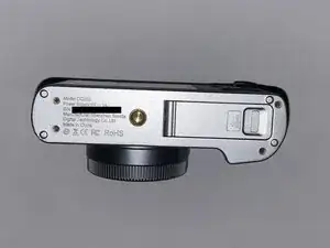
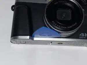
The camera has a model number of DC202 and is manufactured by Shenzhen Sonida Digital Technology Co., Ltd.
-
-
-
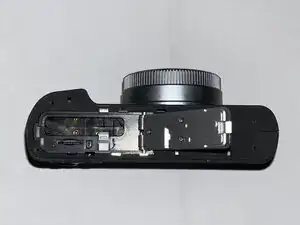
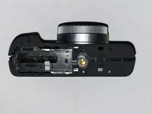
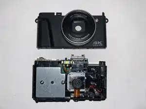
Time to start the teardown! Let's start by removing the bottom cover.
-
This revealed almost nothing about the insides of the camera, but did reveal that the rest the case (minus the silver plastic top cover) is split into two halves.
-
-
-
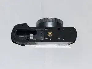
I spot screws! Disassembling the battery door revealed some springs, but that's just about it.
-
-
-
I stalled trying to figure out what to do next. I undid the two screws on the top cover, which didn't appear to do anything, so I tried separating the halves of the main part of the case. They separated all right, but they were still caught at the top.
-
-
-
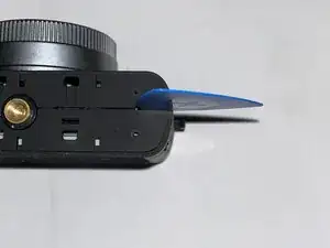
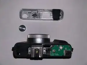
Breakthrough! I discovered that the top cover pops off almost as easily as the bottom cover (held on by just a few clips once the screws were removed).
-
-
-
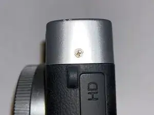
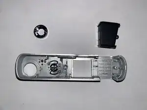
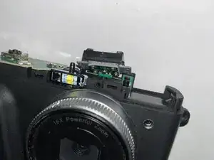
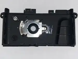
Inside the top cover, I found that the viewfinder and the ring around the power button were screwed in from the underside.
-
-
-
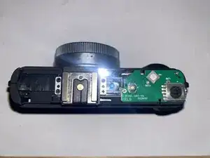
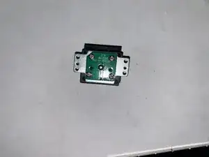
The top cover revealed some circuitry, but removing the screws only allowed be to look underneath: both boards visible are soldered to the logic board.
-
-
-
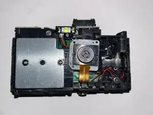
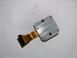
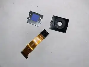
Camera, you're first! Removing and disassembling the camera module revealed that the component itself is tiny compared to the rest of the device.
-
The camera, labelled OV8865AF-FPC-V10-LF, is capable of taking photos at 3264 x 2448 (8 megapixels) at 30FPS. It can also record video at 1080p at 30FPS or half the resolution for double the FPS.
-
-
-
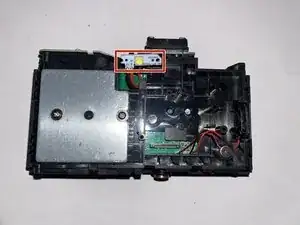
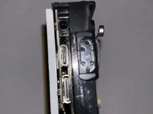
Removing the flash cover revealed more screws to remove the flash module, which is soldered to the logic board with two wires.
-
-
-
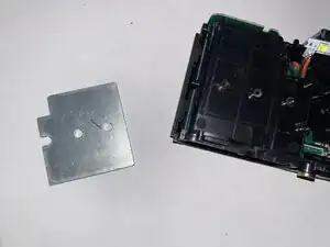
I was disappointed to learn that removing this metal plate, which turned out to be a weight, didn't reveal any screws or components.
-
-
-
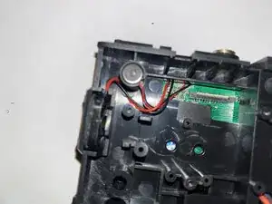
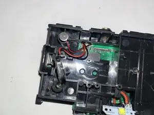
The microphone popped out with ease, but the speaker is glued in with a gasket of adhesive. While the adhesive is light, the speaker's positioning makes it more difficult to remove than it would've been if it could've been pried straight out.
-
-
-
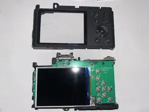
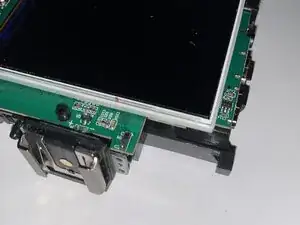
Time to remove the front cover! This revealed several buttons along with the screen.
-
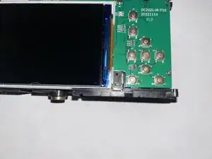
I removed a screw near the bottom-left of the display that seemed to only hold down a small metal cover.
-
-
-
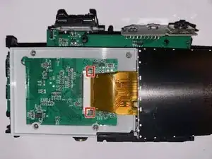
Unplugging the display cable requires the black tabs to be pulled out pulling out the cable.
-
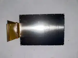
Removing the screws around the display frame let the logic board free.
-
-
-
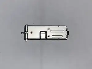
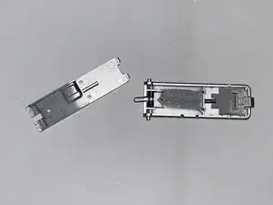
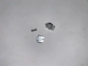
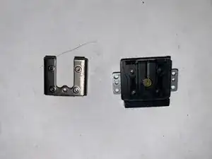
Some parts fell off while I was disassembling the device. The first picture shows the tiny metal cover and the battery locking mechanism, and the others are of the hot shoe that was soldered to the motherboard.
-
-
-
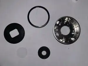
Taking apart the back case separates some plastic bits from a gasket and the glass. (Yes, it's real glass.)
-
-
-
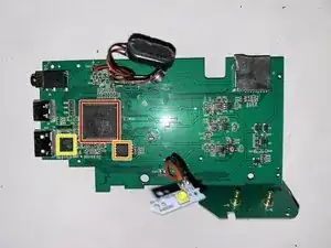
Finally! The logic board!
-
On the front:
-
2301 LUL083 PM230102 or 2301-EUL083 PM230102- probably an SoC or microcontroller.
-
PZS032SH 2KITA20 made by PLM
-
JL5001A 2101-BXA A1769G
-
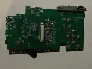
On the back:
-
Not much! The board is labeled DC202L-M-V10 20221114 XLD. Searching for it on Google didn't show any results, so I'm guessing this is just for part identification within Sonida.
-