Introdução
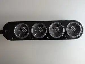
A teardown of the Shelly Power Strip 4 Gen4 (hardware version 1.0.0).
-
-
There are 4 type F sockets
-
Each socket is rated for 12A
-
Each socket has individual metering and switching
-
-
-
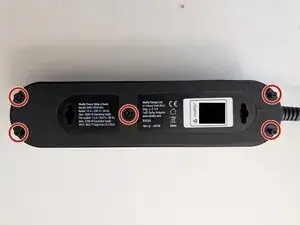
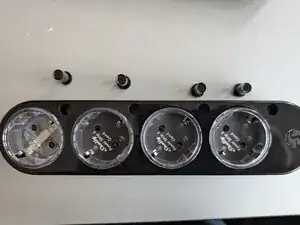
On the back there are 5 screws.
-
They are hidden below a easy to remove rubber mat.
-
You'll need a triangle size 2 Screwdriver
-
-
-
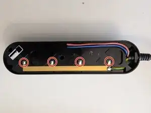
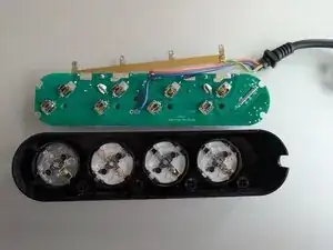
Next you can see the ground bus bar.
-
The earth connectors of the sockets are riveted on the socket side (below the labels).
-
The only easy way to continue disassemling is to unsolder the earth bus bar on the back on the 4 soldering points going to the top (See red circles).
-
-
-
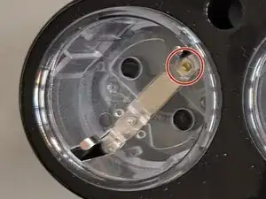
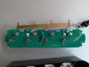
The bottom facing side of the PCB is not very interesting.
-
It only contains the connector clamp contacts and two 3.58 Mhz crystal needed for the metering ICs.
-
-
-
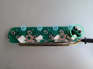
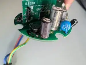
On the top facing side all the magic happens
-
There are 4 switches (blue circles) on the PCB which are extended to the top.
-
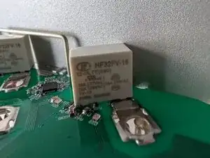
4 relays (white boxes)
-
2 Analog Devices ADE7953 metering ICs
-
A switching regulator for the control circuit (green circle).
-
A 90° angled extra PCB containing the microcontroller.
-
-
-
Relay type: HONGFA HF32FV-16/12-HLTF(590). hon3 x 104OPS(16A 250VAC,Resistive oad,85,1s on 9s off)TV-8, TV-10, TV-12
-
Rated for 3 x 10^4 switching operations at 16A 250V AC (Resistive load)
-
They use the "590 special code" version which has TV-12 contact rating (up to 120A inrush current support for capacitive loads).
-
The official 12A rating/limit seems to contain some extra safty margin to avoid contact welding.
-
The relays are possitioned so they perfectly fit into the triangle area on the opposite side of the button. There's an air gap of 3mm over the relays. While this certainly limits the ventilation of the relays it results in a very compact design.
-
Adding temperature sensors to the relays would have been nice to detect overheating relays.
-
-
-
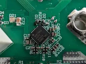
The metering is done using two Analog Divice ADE7953 ICs.
-
The ICs have two current meassuring channels which are supposed to meassure phase and neutral current in single phase applications. Shelly makes use of them to meassure the current of two seperate outlets instead.
-
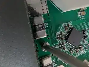
The current is directly meassured using a 1 mΩ shunt resistor
-
The 3.58 MHz crystals are on the opposide PCB side (probably due to limited space on the top side of the PCB).
-
-
-
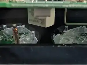
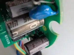
The switch power supply on the cable inlet side provides 12V DC for the relays and 3.3V for the microcontroller.
-
A 10µF and a 4.7µF 400V electrolytic capacitor is used on the primary side
-
A 330µF 16V electrolytic capacitor is used for the 12V secondary side.
-
Using solid capacitors on the secondary side would have been nice to archive a longer lifetime.
-
-
-
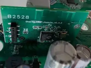
The microcontroller PCB contains the ESP-Shelly-C68F
-
An unused 7 pin 1.27mm pitch header which can most like be used to easily reprogram the flash of the microcontroller is also present.
-
Changing the firmware to ESPhome/Tasmota should be possible without to much trouble.
-