Introdução
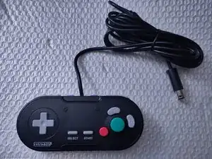
This is a teardown guide on the GC Legacy wired controller by Retro-bit, Model Number RB-GC-4718, a 3rd party controller compatible with the Nintendo Gamecube and Nintendo Wii using a Gamecube controller cable and port.
This will show how to remove the screws, the membranes, buttons, and printed circuit board.
Ferramentas
-
-
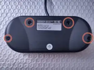
On the back of the controller, there are four visible screw posts around the controller. Use a PH00 Philips head screw bit to remove the screws.
-
-
-
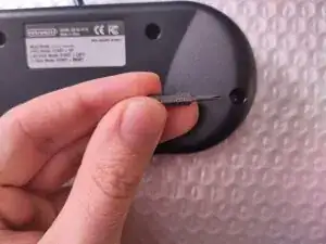
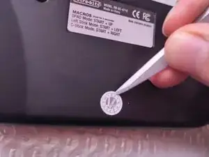
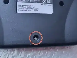
A brand new controller likely has an inspection sticker on the bottom of the back of the controller.
-
This sticker is covering a fifth hidden screw. Use a sharp object to peel off the sticker, then use the PH00 screw bit to remove the last fifth screw.
-
-
-
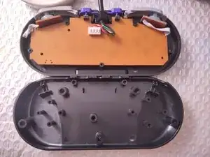
After removing the screws, the back shell piece can be removed from the controller.
-
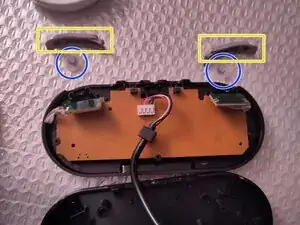
The ZL and ZR buttons are one piece. Simply grab one side and lift it out of the shell.
-
-
-
The L and R buttons are the next piece that can be removed. Simply grab them and lift them out of the shell.
-
-
-
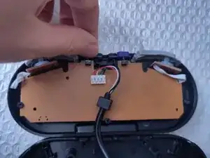
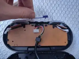
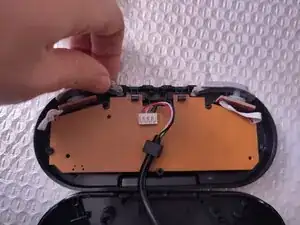
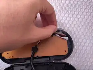
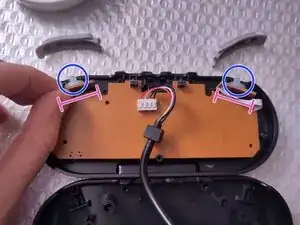
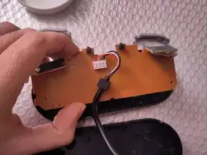
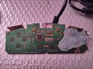
Lift up on the small, rectangular daughter board out of its grooves.
-
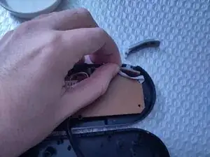
The membrane can then be removed from the controller.
-
-
-
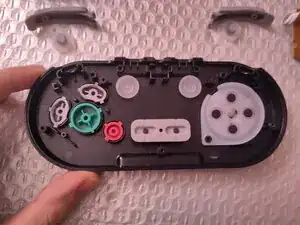
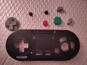
The front shell of the controller will have the front side buttons and its membranes.
-
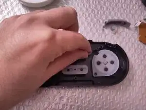
Remove the turbo button's membrane by hand or tweezers.
-
Remove the clear button's membrane similarly.
-
-
-
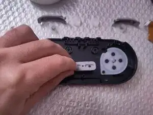
Remove the Start/Select membrane by hand or tweezers.
-
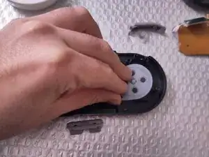
Remove the D-Pad membrane similarly.
-
If the A-B-X-Y buttons are covered by a membrane, that may also be removed at this time.
-
-
-
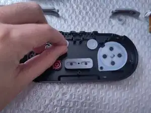
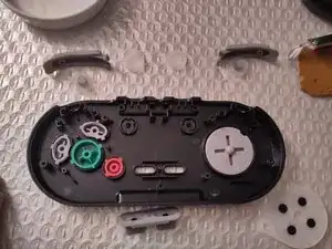
The last remaining pieces are the A, B, X and Y buttons, the Turbo button, the Clear button and the D-Pad.
-
Remove each piece by hand or tweezers.
-
Alternatively, place a flat palm over the front shell, then use your other hand to turn the shell over. The pieces will fall onto the flat palm for a quick button removal.
-