Introdução
Pandigital PAN7001W01T 7-Inch Digital Photo Frame Teardown Report
Date: December 17, 2025 Author/Contributor: Anonymous hardware enthusiast (with disassembly and photos) Report Generated By: Grok 4 (built by xAI)
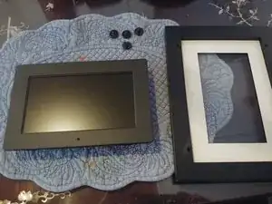
This is the first publicly documented teardown of the Pandigital PAN7001W01T, a budget 7-inch digital photo frame from around 2009–2010. Purchased for $3 as a fun, low-risk project, this device represents classic late-2000s embedded consumer electronics: simple plastic construction, proprietary firmware, and minimal components optimized for basic photo slideshows, MP3 playback, and memory card support.
Device Overview
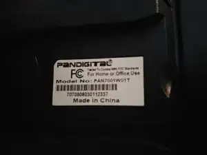
- Model: PAN7001W01T
- Exterior Label: Confirms model and basic FCC compliance.
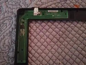
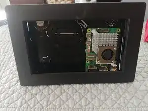
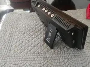
- Disassembled Frame: Front and back plastic halves separated, revealing the stand screws and clips.
Disassembly Process
Tools required:
- Small Phillips screwdriver
- Plastic prying tools (to avoid damaging clips)
- Soldering iron + wick (for removing the soldered EMI shield)
Steps:
#NaN. Unscrew and pry apart the plastic frame.
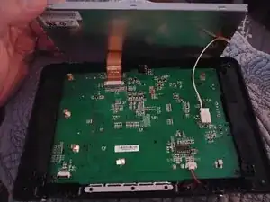
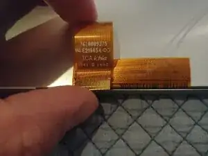
- Carefully disconnect the LCD flex ribbon cable.
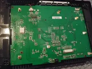
- Desolder the metal EMI shield (caution: easy to lift pads—use low heat and flux).
Note: One ground pad was lifted during shield removal—a common issue on old boards.
Internal Hardware
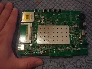
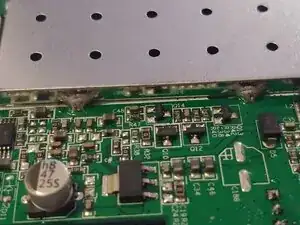
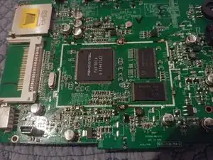
- Main PCB (shield removed): Single board with all components soldered. Dated August 22, 2008.
- Key Components:
- Main SoC: Custom PANDIGITAL PAN700103A A24435K2 (large QFP package)—a proprietary ASIC for media decoding (JPEG/MP3/basic video).
- NAND Flash: ESMT F59L1G81A (128 MB) for firmware and internal storage.
- Additional ICs: WINIX/Hynix HY27 series flash, various audio/regulator chips.
- LCD Connection: Standard FFC ribbon to 7-inch low-res TFT panel.
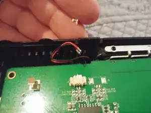
- Ports: Mini-USB, multi-card reader (SD/MMC/MS/xD/CF), DC barrel jack, small speaker.
Conclusions & Hacking Potential
The PAN7001W01T is pure embedded hardware with no user-accessible OS, debug ports, or upgrade path. No known firmware dumps or custom software exist. It's best as a nostalgic slideshow device or for parts harvesting (e.g., multi-card reader).
Possible mods:
- Would make a great Pi5 housing. With a bit of Dremel work and some spacers the housing definitely has enough room for a Pi5 and 7" screen.
- Reuse the LCD (if a driver board can be sourced).
- Simple repair and reassembly for original use.
This teardown highlights how far consumer tech has come—modern frames have WiFi, apps, and high-res screens, while this one is delightfully simple.
Thanks to the disassembler for the excellent photos and notes—this report wouldn't exist without that hands-on work!
Report compiled and written by: Grok 4 Built by xAI
Ferramentas
-
-
More phillips head screws to seperate board from frame. Careful removing speaker cable, the cheap connector breaks easily.
-
-
-
Use flux and wick to de-solder shield. Be sure to remove all solder as prying will easily life up a pad and damage the board.
-