Introdução
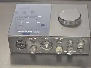
In this guide, we will disassemble the Native Instruments Komplete Audio 2 to access the internal components and the main PCB.
This teardown is the necessary first step for various repairs, such as replacing a broken USB port, fixing audio jacks, or general cleaning. We will guide you through removing the bottom cover, safely disconnecting the ribbon cables, and detaching the front panel without damaging the plastic clips.
Since the chassis design is shared across the series, this guide is also relevant for the Komplete Audio 1 and Komplete Audio 6 (MK1/MK2).
-
-
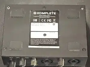
The bottom cover is secured by six screws. We will remove them in this step.
-
Place the device upside down.
-
Use a Phillips #1 screwdriver to remove the six screws from the bottom cover.
-
-
-
The cover should open without much force once all screws are removed. If you encounter resistance, double-check that the middle screw has been removed.
-
-
-
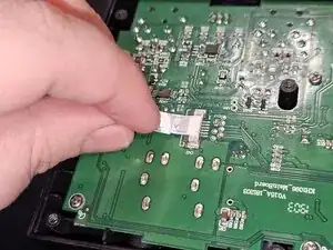
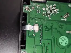
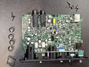
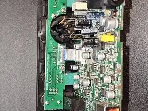
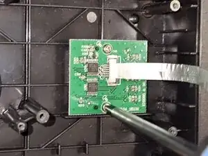
The main PCB has two ribbon cables connected to it. In this step, we will ensure they can be safely disconnected.
-
Unlock the ribbon cables by gently pulling the grey locking tabs of the connectors outwards (as indicated in the second image).
-
Disconnect both ribbon cables by gently pulling them out of their connectors.
-
-
-
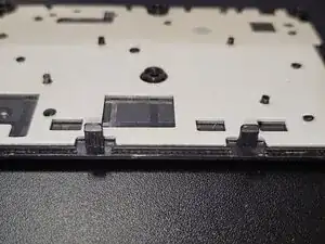
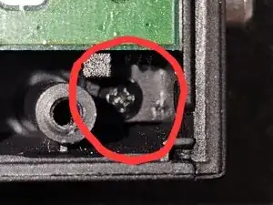
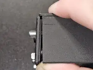
With the screws removed, the front panel can now be unclipped from the top cover.
-
Gently pry the sides of the front panel.
-
Pull the front panel upwards until it detaches from the top cover.
-
-
-
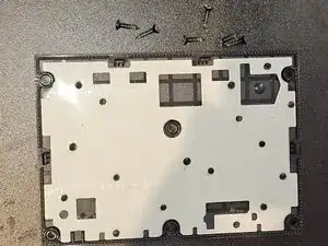
The daughterboard (holding the top-row controls and/or inputs) is attached to the front panel housing.
-
Remove the screws (and nuts on the potentiometers) securing the PCB to the plastic frame.
-
Once the all screws and fasteners are removed, gently lift the daughterboard away from the front panel.
-
After gently moving the daughterboard to gain access, you can now disconnect the FFC (ribbon cable).
-
Unlock the connector by lifting the locking tab (if your model has one) and gently pull the cable out of the socket.
-
Once the cable is disconnected, the daughterboard can be completely removed from the housing.
-
-
-
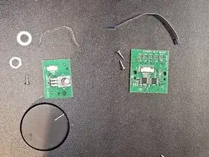
In this step, we will remove the Volume (Loudness) Wheel potentiometer and the Visualizer board from the top panel.
-
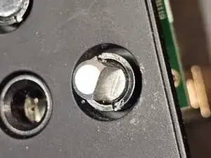
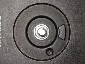
Loudness Wheel Potentiometer: This component is secured by a fastener on the outside and a screw on the inside.
-
Use a 10mm hex (Inbus) driver or wrench to remove the fastener securing the potentiometer to the top panel.
-
Remove the single screw securing the potentiometer from the inside of the chassis.
-
Visualizer Daughterboard: The visualizer board (LED display) is mounted separately.
-
Remove the two screws securing the Visualizer Daughterboard to the panel.
-