Introdução
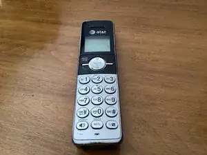
A brief teardown of a basic AT&T cordless handset. Model CL82353.
-
-
This is an AT&T landline phone handset from my Grandfather. I kept it sitting around for a while before I finally decided to take it apart to see what was inside.
-
-
-
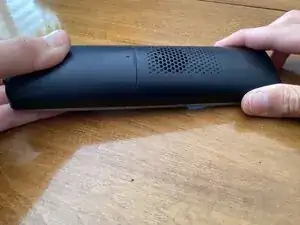
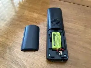
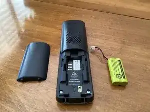
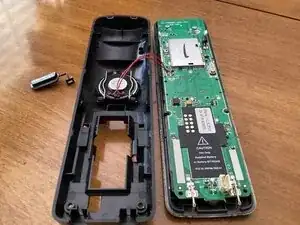
To begin disassembly, pull off the battery cover with your hands. Then, locate the battery connector and remove it by gently pulling on the cable.
-
-
-
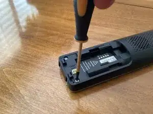
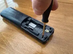
Next, use a Philips screwdriver to remove the two screws from the handset.
-
Be careful not to lose these two screws! Stepping on one will hurt!
-
-
-
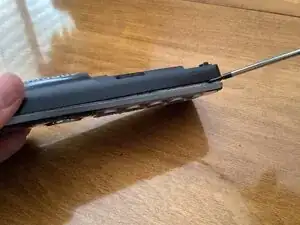
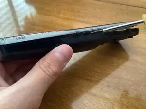
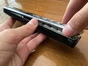
To open the handset, use a flathead screwdriver to pry open the clips holding the handset together.
-
After all of the clips have been released, open the handset by carefully pulling it apart.
-
-
-
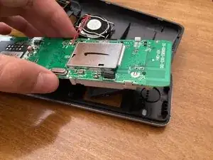
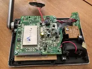
After the case has been opened, you can now see the PCB and the speaker. ( If you already haven’t noticed, the microcontroller is under an RF shield to prevent from interference.)
-
-
-
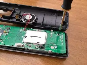
To remove the PCB, use a Philips screwdriver to remove the two screws securing it. Then you can lift up the PCB and separate it from the plastic frame.
-
-
-
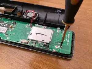
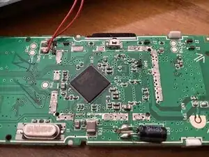
Before, I removed the PCB, I decided to remove the metal shield to see the microprocessor SoC. It is from DSP group.
-
Also under the metal shield are some random RF components and inductors.
-
-
-
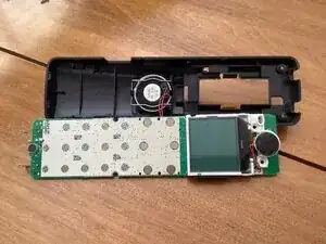
Now you can finally see the other side of the PCB in all its glory, with no important components whatsoever, except for a lone microphone and the awful LCD screen.
-
-
-
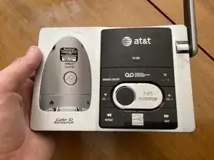
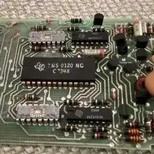
Here’s the phone base station.
-
I was too lazy to make a teardown on this, so I just took it apart and took a picture of the PCB inside.
-
Anyways, that’s the end of the teardown. Thanks for viewing if you did.
-
Um comentário
Hi it is cool