Introdução
⚠⚡ This device contains high voltage capacitors. Wear high voltage PPE when the main circuit board is exposed.
ℹ This device uses three different lengths of Phillips head screws.
ℹ The devices shown in this guide already has the power cable removed. This does not change any steps.
Ferramentas
-
-
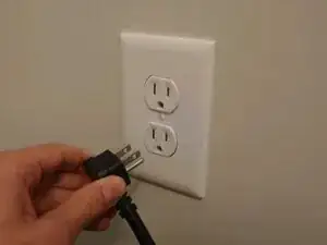
Safely shut down and unplug all devices connected to the UPS.
-
Hold the power button to power the UPS off.
-
-
-
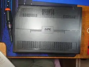
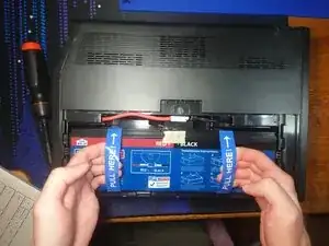
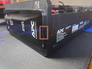
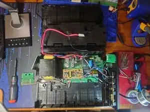
Lay the UPS on its side. (Validate the orientation using the picture)
-
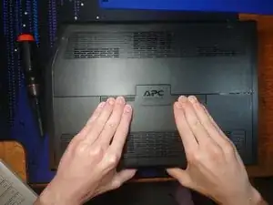
Push down hard on both sides of the APC logo.
-
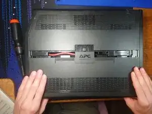
Pull the slide cover towards you to remove.
-
-
-
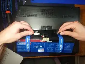
Pull on the battery pull tabs with the cables still attached. (In the picture the cables are already disconnected)
-
There should be enough slack in the cables to set the battery back down at an angle. This will let you access both cables.
-
Unplug both cables. Preferably unplug red first.
-
-
-
Turn the UPS so the screen faces you.
-
Stick a spudger in the cutout (outlined in red) to release the plastic snaps.
-
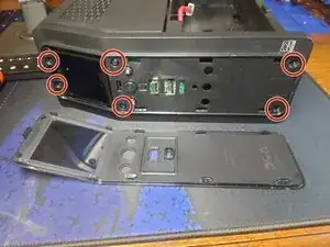
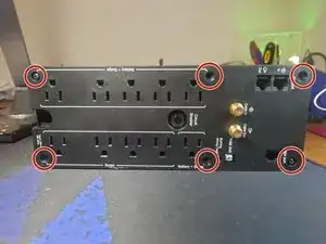
Remove the 6 phillips head screws (circled in red).
-
Pull the face plate toward you to remove. It should take very little effort to remove.
-
The buttons are captive and will not fall out.
-
-
-
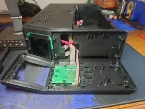
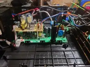
Remove the two phillips head screws (circled in red).
-
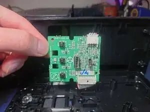
Lift the low-voltage circuit board to remove it. Note: It pivots at the bottom.
-
You may remove the connectors on the circuit board. Refer to this guide for removing connectors: Recognizing & Disconnecting Cable Connectors
-
-
-
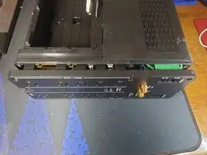
Turn the UPS with the back facing you.
-
Remove the 6 phillips head screws.
-
Pull the backplate towards you to remove. It is connected to many wires and could take some effort to get loose. You cannot fully remove it.
-
The back plate just needs to be about a centimeter away from the rest of the shell.
-
-
-
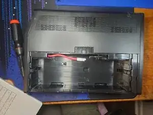
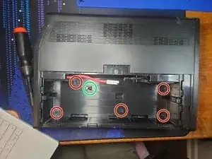
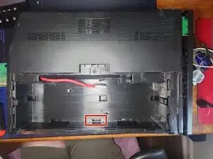
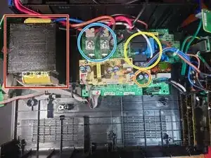
Turn the UPS with the battery compartment facing you.
-
Insert a plastic spudger into the bottom middle hole (outlined in red) to separate the plastic snap.
-
There are no high-voltage components in this area.
-
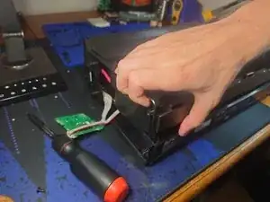
Pull up on the plastic shell to release it.
-
There are small plastic snaps at the top of the UPS but pulling hard enough should release them without breaking.
-
Once the shell is free, remove the cables from the battery compartment. The red wire may take some wiggling but it will fit through the hole.
-
-
-
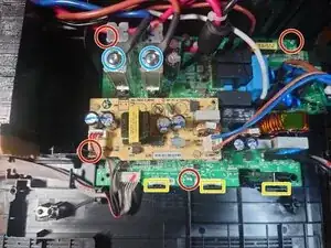
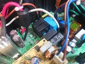
Unplug all wires from the circuit board. Some are very difficult to remove.
-
Unscrew the 2 Torx T25 screws (circled in blue) on the metal posts to remove the wires.
-
Unscrew the 4 phillips head screws (circled in red).
-
Release the plastic snaps (outlined in yellow). You may need to pull up on the board to keep the snaps released. The board will pivot at the top.
-