Introdução
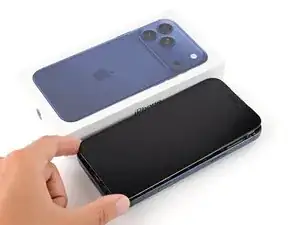
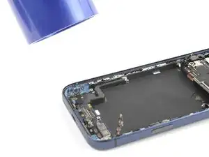
Follow this guide to remove and replace the USB-C port assembly in an iPhone 17 Pro Max. If you experience intermittent connectivity or charging with the port, you may need to replace it.
This procedure requires extensive disassembly. Before you replace the USB-C port, try cleaning it out first. Rule out any software culprits or other hardware possibilities.
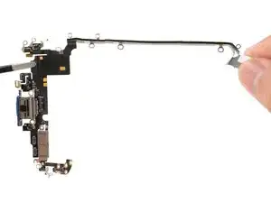
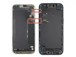
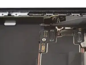
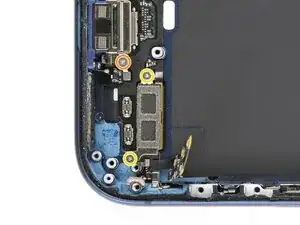
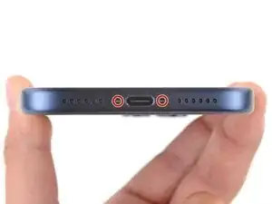
The USB-C port assembly includes the USB-C port, a microphone, and antennas.
Ferramentas
-
-
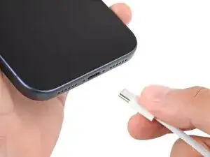
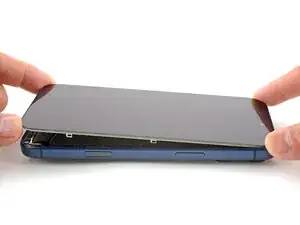
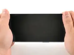
Unplug all cables from your phone.
-
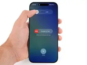
Hold the power and either volume button and slide to power off your phone.
-
-
-
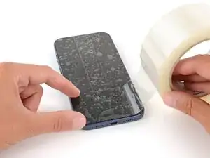
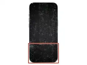
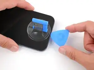
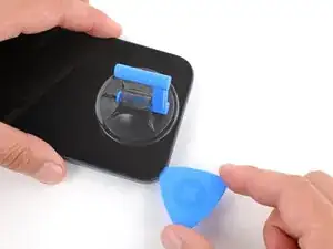
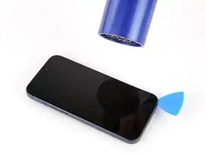
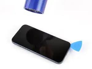
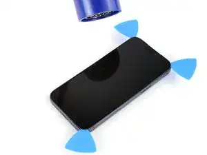
Apply strips of packing tape to the cracked glass until it's completely covered—this will help keep the glass contained and allow the suction cup to stick.
-
Make sure there's a single strip of tape (not overlapping) across the bottom edge, big enough for a suction cup to fit on.
-
-
-
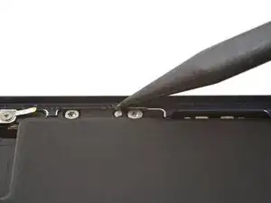
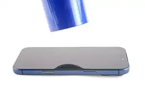
Use a P2 pentalobe screwdriver to remove the two 7.5 mm‑long screws on either side of the charging port.
-
-
-
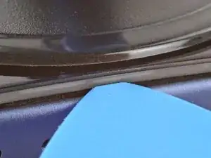
Use a hair dryer or heat gun to heat the bottom edge of the screen until it's slightly too hot to touch.
-
-
-
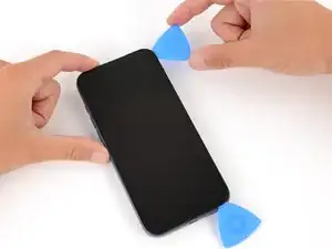
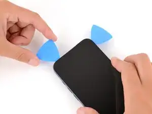
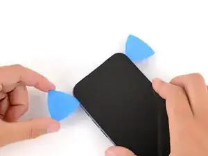
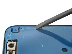
There's a plastic bezel on the underside of the screen that sits on the frame. Insert your pick here, making sure it's completely under the bezel.
-
There's a seam between the plastic bezel and the display panel. Don't insert your pick here or you'll separate the two, complicating the repair.
-
-
-
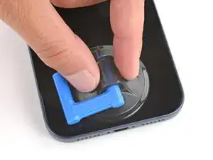
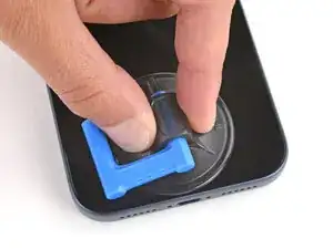
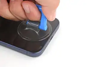
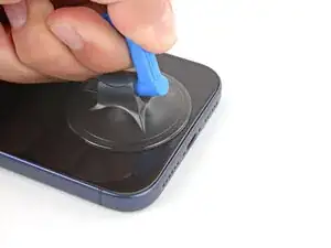
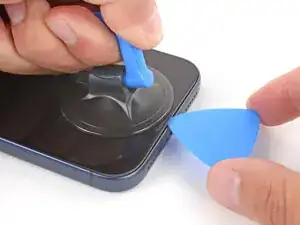
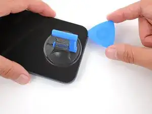
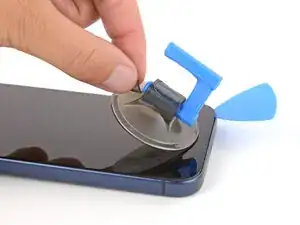
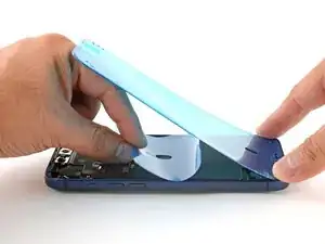
Pull up on the suction handle with strong, steady force until a gap forms between the screen and frame.
-
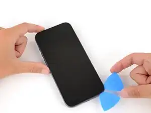
Insert the tip of an opening pick in the gap you just created.
-
-
-
The screen and ambient light sensor cables are located near the volume and Action buttons.
-
There are delicate spring contacts around the perimeter of the phone.
-
The underside of the screen has thin, metal clips that go into corresponding slots on the frame.
-
-
-
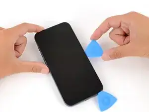
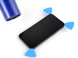
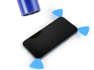
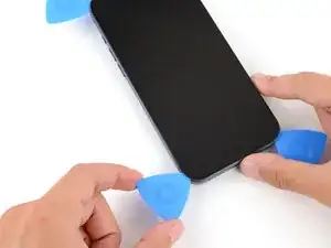
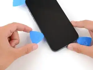
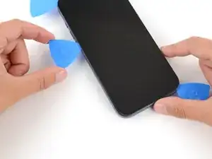
Slide the opening pick along the bottom edge to separate the adhesive.
-
Leave the pick inserted under the bottom right corner to prevent the adhesive from re‑sealing.
-
-
-
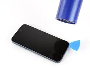
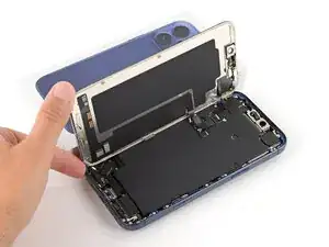
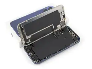
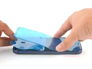
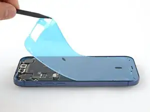
Lift the screen straight up and swing it over the left edge, propping it up against a sturdy box or stack of books so the cables aren't strained.
-
-
-
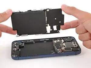
Use a JIS 00 screwdriver to remove the two 1.2 mm‑long screws securing the battery and screen cable covers (one for each cover).
-
-
-
Use the tip of an opening pick or the point of a spudger to pry up and disconnect the screen and front sensors press connectors.
-
-
-
Use a Torx Plus 4IP screwdriver to remove the screws securing the battery tray:
-
One 7.5 mm‑long screw
-
One 5.9 mm‑long screw
-
One 3.5 mm‑long screw
-
One 2.4 mm‑long screw
-
Ten 3.7 mm‑long screws
-
One 3.7 mm‑long screw
-
-
-
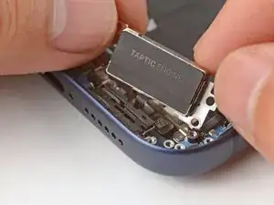
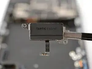
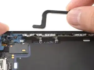
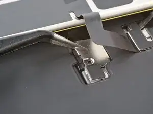
Slide the tip of an opening pick along the top edge of the Taptic Engine to separate the plastic buffer strip adhered to it.
-
-
-
Use a JIS 00 screwdriver to remove the six screws securing the loudspeaker:
-
Two 2.7 mm‑long screws
-
Two 2.0 mm‑long screws
-
One 1.5 mm‑long screw
-
One 1.5 mm‑long screw attached to the bottom edge
-
-
-
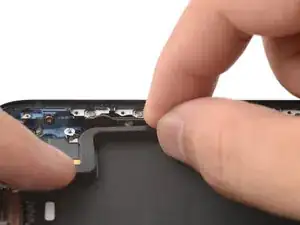
Tilt the top edge of the loudspeaker out of its recess.
-
Slowly pull the loudspeaker away from the frame to release the adhesive.
-
Remove the loudspeaker.
-
-
-
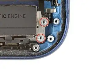
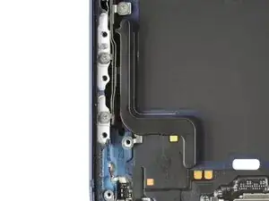
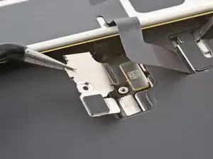
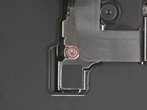
Use a JIS 00 screwdriver to remove the three screws securing the flex antenna:
-
One 1.7 mm‑long screw
-
Two 1.9 mm‑long screws
-
-
-
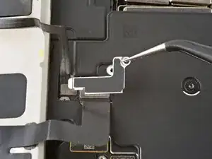
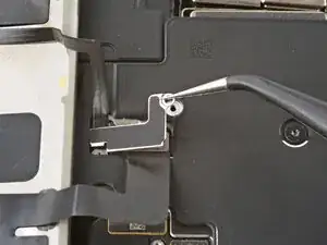
Use your fingers or a spudger to swing the flex antenna out of the way to access the screws beneath it.
-
-
-
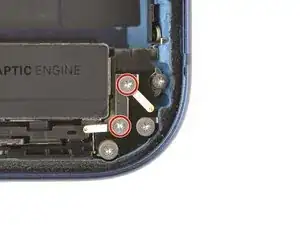
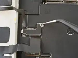
Use a standoff screwdriver to remove the two 4.0 mm‑long screws securing the Taptic Engine.
-
-
-
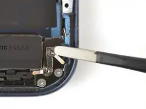
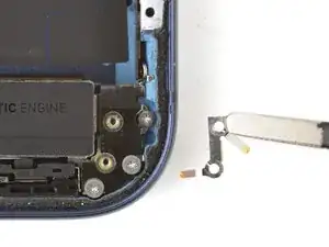
Use your fingers to flip the Taptic Engine out of its recess and onto the edge of the iPhone.
-
Hold onto the Taptic Engine during the next step to prevent straining its cable.
-
-
-
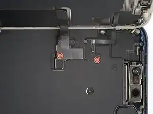
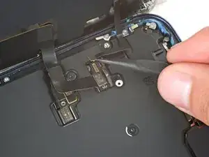
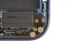
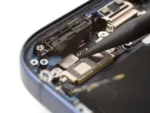
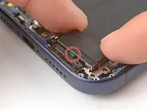
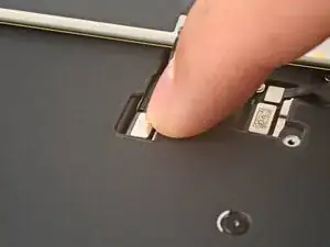
Remove the two screws securing the lower microphone:
-
One 3.2 mm-long standoff screw
-
One 3.1 mm-long JIS 00 screw attached to the bottom edge of the iPhone frame
-
-
-
Use a hair dryer or an iOpener to heat the bottom-right corner of the iPhone until it's warm to the touch.
-
-
-
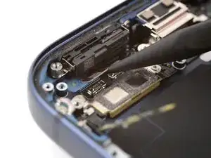
Insert the point of an opening pick between the lower microphone and the frame.
-
Slide the pick along the edge to create a gap between the microphone and the frame.
-
-
-
Insert the flat edge of a spudger into the gap between the lower microphone and the frame.
-
Twist the spudger slowly to pry the microphone off the frame.
-
Remove the lower microphone.
-
-
-
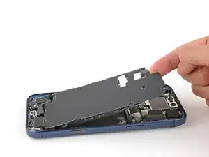
Use a hair dryer or an iOpener to heat the black plastic battery buffer until it's warm to the touch.
-
-
-
Use the flat end of your spudger to pry up one end of the battery buffer.
-
Grab the buffer with your fingers and slowly lift and remove it.
-
-
-
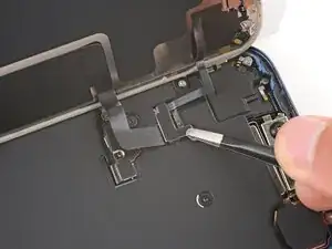
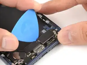
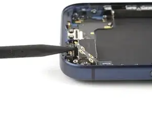
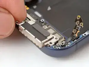
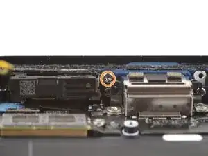
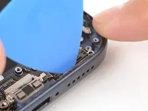
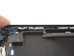
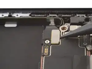
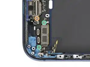
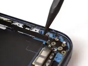
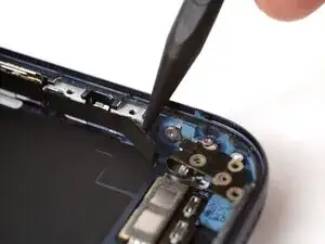
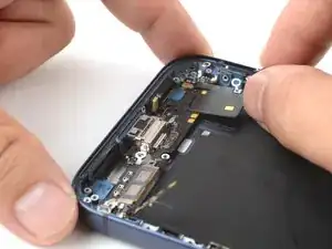
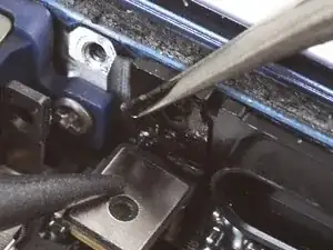
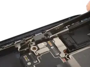
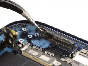
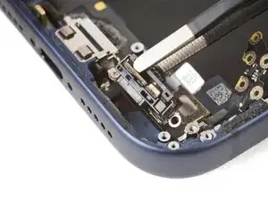
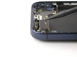
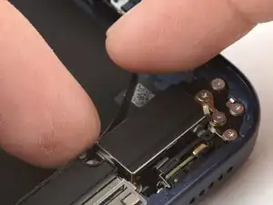
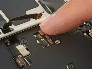
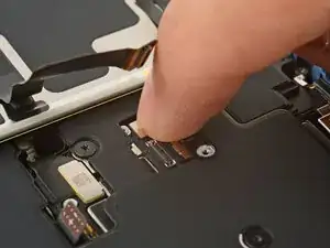
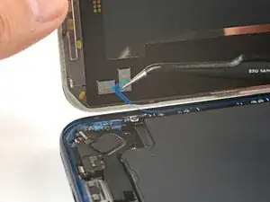
Use the point of a spudger to pry up and disconnect the two USB-C press connectors (one's underneath the other) from the bottom-left corner of the logic board.
-
-
-
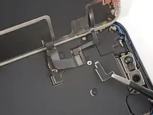
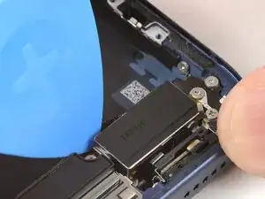
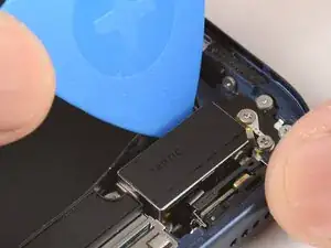
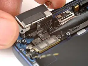
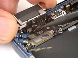
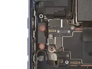
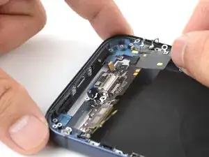
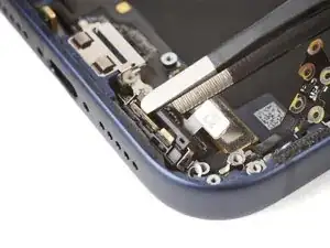
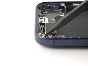
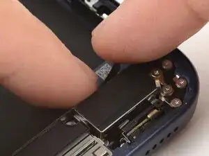
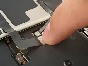
Use a JIS 00 screwdriver to remove the two 1.8 mm‑long screws securing the left logic board buffer.
-
-
-
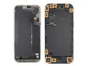
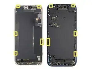
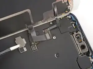
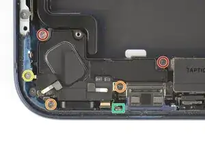
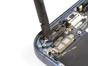
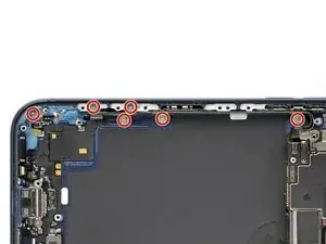
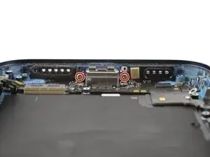
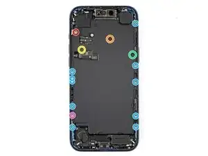
Remove the nine screws securing the USB-C port assembly:
-
Six 1.5 mm‑long JIS 00 screws
-
One 1.3 mm‑long JIS 00 screw
-
Two 1.2 mm‑long Y000 screws
-
-
-
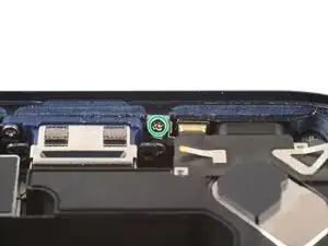
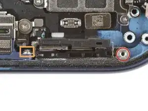
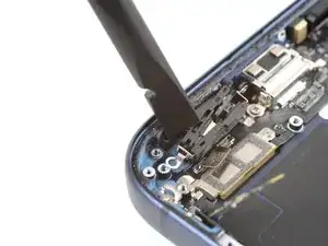
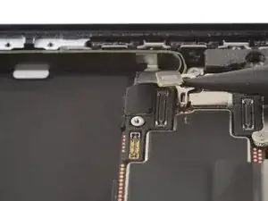
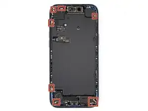
Use a JIS 00 screwdriver to remove the 1.2 mm‑long screw securing the USB-C port assembly to the bottom left corner of the frame.
-
-
-
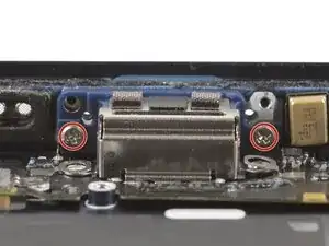
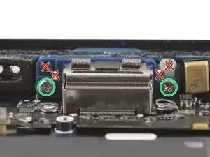
Use a JIS 00 screwdriver to remove the two 2.8 mm‑long screws securing the USB-C port to the bottom edge of the frame.
-
-
-
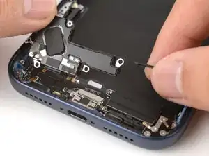
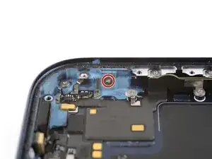
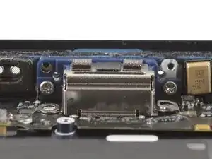
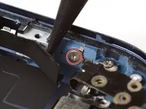
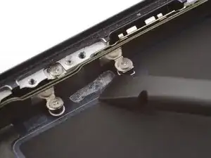
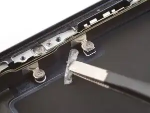
Use the point of a spudger to pry and separate the buffer strip covering the screw in the bottom right corner of the frame.
-
-
-
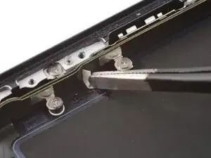
Use a JIS 00 screwdriver to remove the 1.2 mm‑long screw securing the USB-C port assembly to the right edge of the frame.
-
-
-
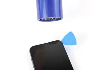
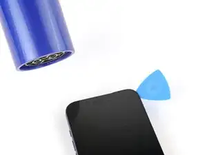
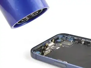
Use a hair dryer or an iOpener to heat the entire USB-C port assembly until it's warm to the touch.
-
-
-
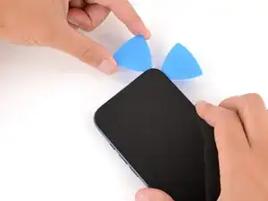
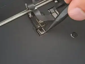
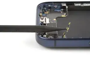
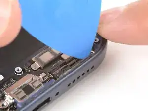
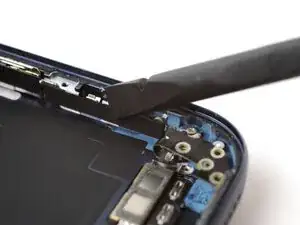
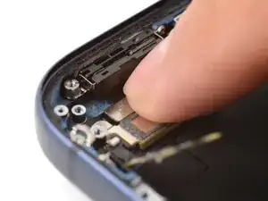
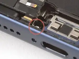
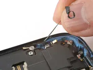
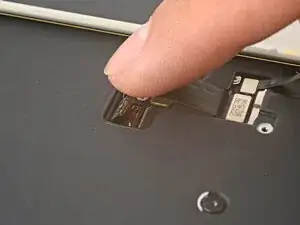
Slide the point of an opening pick between the microphone module (left of the USB-C port) and the bottom edge of the frame.
-
Pry gently to separate the microphone from the frame.
-
-
-
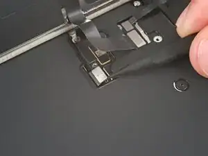
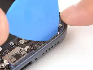
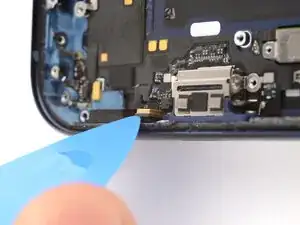
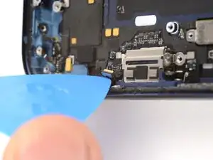
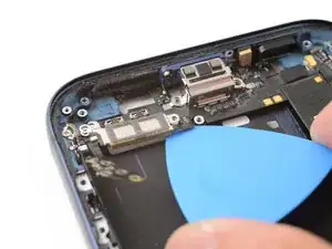
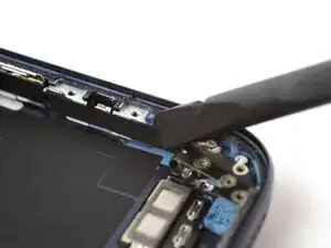
Slide the opening pick under the USB-C port assembly, near the center.
-
Slide the pick towards the right edge of the frame to separate the adhesive holding the assembly.
-
-
-
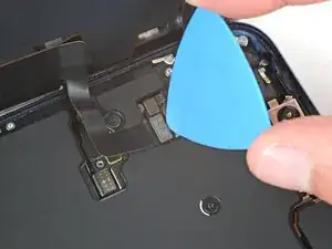
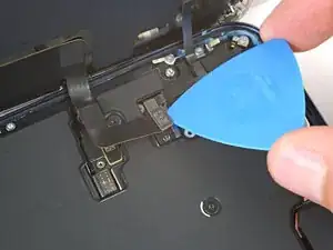
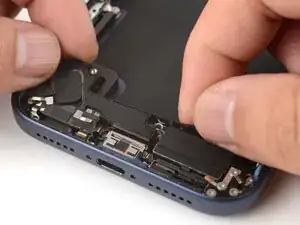
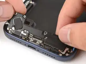
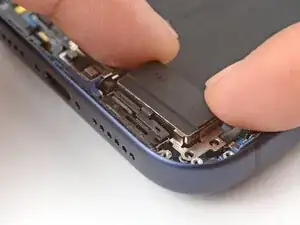
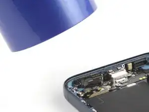
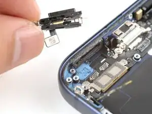
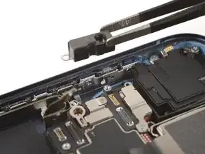
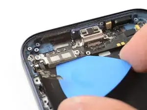
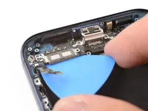
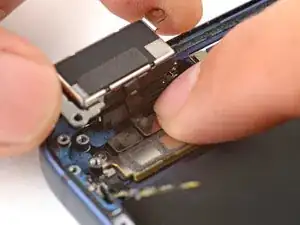
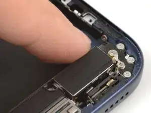
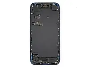
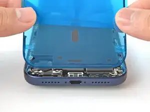
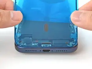
Grab the USB-C port assembly with your fingers and slowly pull it away from the frame to remove it.
-
-
-
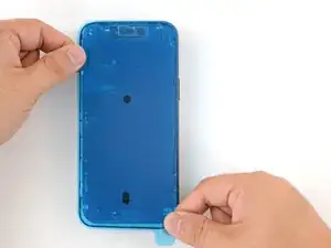
Carefully inspect your replacement USB-C port assembly and remove any adhesive liners.
-
Align the assembly with the bottom edge of the frame and place it loosely in place.
-
-
-
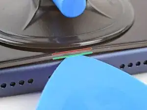
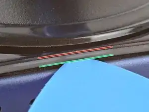
Use a JIS 00 screwdriver to install the two 2.8 mm‑long USB-C port screws to the bottom edge of the frame.
-
Make sure to install these screws in the holes marked in green, not red.
-
-
-
Install the nine USB-C port assembly screws:
-
Six 1.5 mm‑long JIS 00 screws
-
One 1.3 mm‑long JIS 00 screw
-
Two 1.2 mm‑long Y000 screws
-
-
-
Use a JIS 00 screwdriver to install the 1.2 mm‑long USB-C port assembly screw to the bottom left corner of the frame.
-
-
-
Use a JIS 00 screwdriver to install the 1.2 mm‑long USB-C port assembly screw to the right edge of the frame.
-
-
-
Use a spudger or your finger to press the buffer strip back onto the frame. It should cover the screw you just installed.
-
-
-
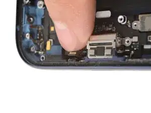
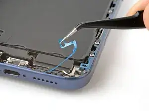
Use tweezers to remove the adhesive from where the microphone attaches to the frame.
-
Use your finger to align and press the microphone module onto the frame.
-
-
-
Use a hair dryer or an iOpener to heat the entire USB-C port assembly until it's warm to the touch. This helps the adhesive to bond better.
-
-
-
Inspect the existing battery buffer adhesives on the frame. If they're still tacky and not deformed, you can reuse them.
-
To replace the adhesives:
-
Use a spudger and tweezers to remove the adhesives. Be careful not to scrape the delicate graphite sheet.
-
Replace the adhesives with some double-sided tape.
-
-
-
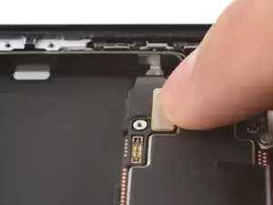
Use your fingers to lay the battery buffer in place.
-
Press down on the buffer for a few seconds to secure it.
-
-
-
Use a hair dryer or an iOpener to heat the battery buffer until it's warm to the touch. This helps improve the adhesive bond.
-
-
-
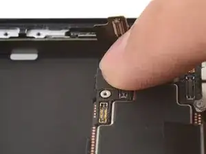
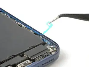
Use tweezers to align the microphone with the frame.
-
Slide the microphone into its recess and press it in place. There should be almost no gap between the microphone and the frame.
-
-
-
Use a hair dryer or an iOpener to heat the lower microphone until it's warm to the touch. This helps strengthen the adhesive bond.
-
-
-
Install the two lower microphone screws:
-
One 3.2 mm-long standoff screw
-
One 3.1 mm-long JIS 00 screw attached to the bottom edge of the iPhone frame
-
-
-
Place the Taptic Engine upside down on the edge of the iPhone frame.
-
While holding the Taptic Engine with one hand, use your finger to press and connect the Taptic Engine press connector.
-
-
-
Flip the Taptic Engine over the frame and align it using its screw holes.
-
The Taptic Engine flex cable should fold neatly between the Taptic Engine and the frame.
-
-
-
Use a JIS 00 screwdriver to install the three flex antenna screws:
-
One 1.7 mm‑long screw
-
Two 1.9 mm‑long screws
-
-
-
Align the bottom edge of the loudspeaker with the frame and lay it in its recess..
-
Make sure the bottom-right screw tab seats properly against the frame. Gently bend it if it's out of place.
-
Use your finger to press down on the loudspeaker until it clicks in place.
-
-
-
Use a JIS 00 screwdriver to install the six loudspeaker screws:
-
Two 2.7 mm‑long screws
-
Two 2.0 mm‑long screws
-
One 1.5 mm‑long screw
-
One 1.5 mm‑long screw attached to the bottom edge of the iPhone frame
-
-
-
Use your fingers or a spudger to press the buffer strip back onto the top edge of the Taptic Engine.
-
-
-
Use a Torx Plus 4IP screwdriver to install the battery tray screws:
-
One 7.5 mm‑long screw
-
One 5.9 mm‑long screw
-
One 3.5 mm‑long screw
-
One 2.4 mm‑long screw
-
Ten 3.7 mm‑long screws
-
One 3.7 mm‑long screw
-
-
-
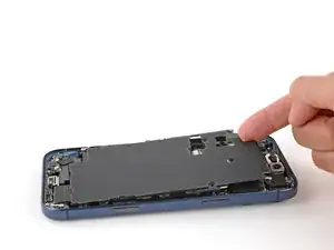
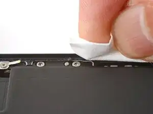
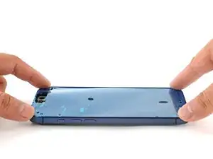
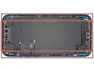
Use a lint-free cloth or a coffee filter to wipe in one direction along the perimeter of the frame to clean the adhesive residue.
-
-
-
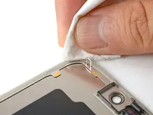
If you're reusing your screen, apply a few drops of highly-concentrated isopropyl alcohol (over 90%) to a microfiber or lint-free cloth and wipe around the perimeter to prepare the surface for new adhesive.
-
-
-
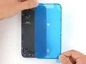
Without peeling any liners, lay the adhesive sheet over the frame to determine its proper orientation.
-
-
-
Grab the tab in the corner of the adhesive sheet and peel the liner to expose a third of the adhesive.
-
-
-
Carefully align the exposed edge of the adhesive strip with the corresponding edge of the iPhone's frame.
-
When it's correctly aligned, gently press the exposed adhesive strip onto the frame.
-
-
-
Continue peeling away the liner from the adhesive, gently pressing the adhesive into place.
-
-
-
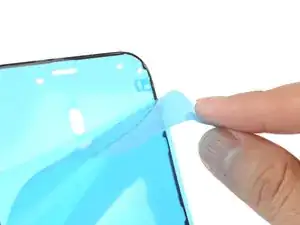
Use the pull tab to peel off the large front liner from the adhesive. The pull tab is often in a corner of the liner.
-
-
-
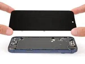
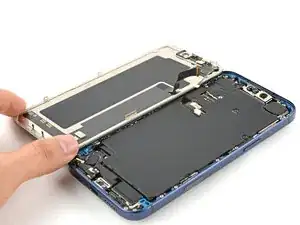
Set the iPhone screen next to the frame such that the screen cables can comfortably reach the logic board.
-
-
-
Use your finger or the flat end of a spudger to press and connect the two screen connectors onto the logic board.
-
-
-
Use your finger or the flat end of a spudger to press and connect the battery connector onto the logic board.
-
-
-
Tuck the top edge of the battery connector cover under the cutout lip.
-
Align the cover by its screw hole and lay it in place.
-
-
-
Use a JIS 00 screwdriver to install the 1.2 mm‑long screw to secure the battery connector cover.
-
-
-
Tuck the left edge of the screen connector cover under the cutout lip.
-
Align the cover by its screw hole and lay it in place.
-
-
-
Use a JIS 00 screwdriver to install the 1.2 mm‑long screw to secure the screen connector cover.
-
-
-
With one hand hold the screen steady.
-
Use your fingers or a spudger to peel away all perimeter liners, exposing the adhesive.
-
Check the internals for any stray liners and remove them. There should be no liners remaining.
-
-
-
Lower the screen onto the frame, beginning with the top edge.
-
Press along the edges of the iPhone until the screen sits flush against the frame.
-
-
-
Use a hair dryer, heat gun, or an iOpener to heat the screen perimeter until it's slightly too hot to touch.
-
-
-
Use a P2 pentalobe screwdriver to install the two 7.5 mm‑long screws on either side of the charging port.
-


Take your e-waste to an R2 or e-Stewards certified recycler.
Repair didn’t go as planned? Try some basic troubleshooting, or ask our Answers Community for help.