Introdução
-
-
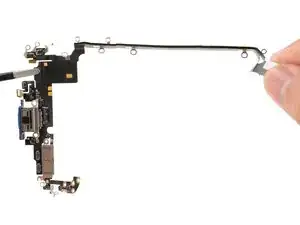
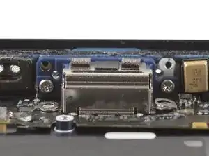
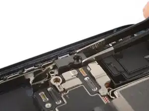
Carefully inspect your replacement USB-C port assembly and remove any adhesive liners.
-
Align the assembly with the bottom edge of the frame and place it loosely in place.
-
-
-
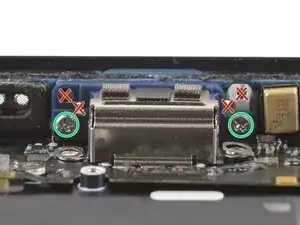
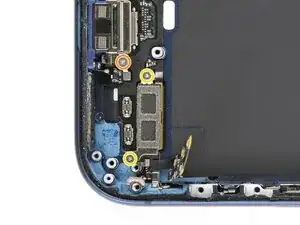
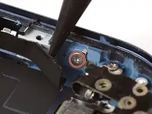
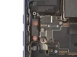
Use a JIS 00 screwdriver to install the two 2.8 mm‑long USB-C port screws to the bottom edge of the frame.
-
Make sure to install these screws in the holes marked in green, not red.
-
-
-
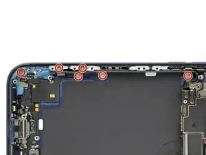
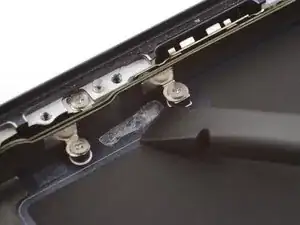
Install the nine USB-C port assembly screws:
-
Six 1.5 mm‑long JIS 00 screws
-
One 1.3 mm‑long JIS 00 screw
-
Two 1.2 mm‑long Y000 screws
-
-
-
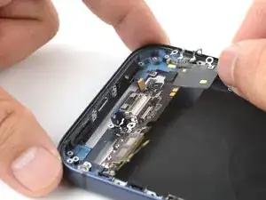
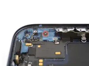
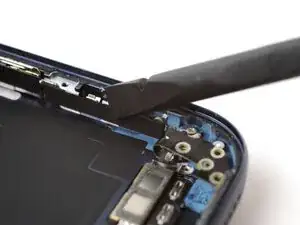
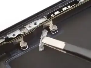
Use a JIS 00 screwdriver to install the 1.2 mm‑long USB-C port assembly screw to the bottom left corner of the frame.
-
-
-
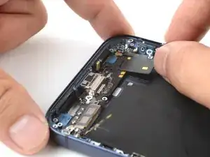
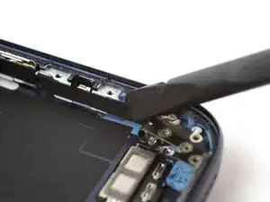
Use a JIS 00 screwdriver to install the 1.2 mm‑long USB-C port assembly screw to the right edge of the frame.
-
-
-
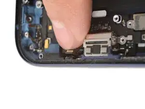
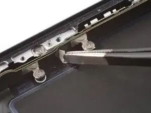
Use a spudger or your finger to press the buffer strip back onto the frame. It should cover the screw you just installed.
-
-
-
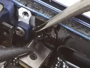
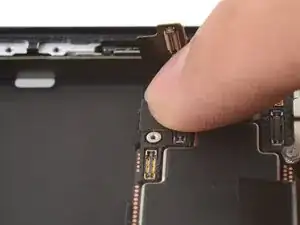
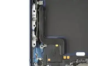
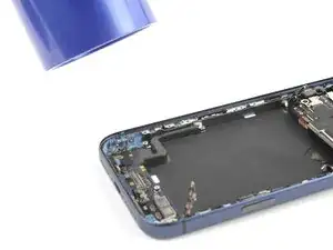
Use tweezers to remove the adhesive from where the microphone attaches to the frame.
-
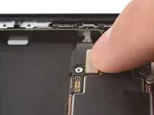
Use your finger to align and press the microphone module onto the frame.
-
-
-
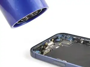
Use a hair dryer or an iOpener to heat the entire USB-C port assembly until it's warm to the touch. This helps the adhesive to bond better.
-
-
-
Inspect the existing battery buffer adhesives on the frame. If they're still tacky and not deformed, you can reuse them.
-
To replace the adhesives:
-
Use a spudger and tweezers to remove the adhesives. Be careful not to scrape the delicate graphite sheet.
-
Replace the adhesives with some double-sided tape.
-
-
-
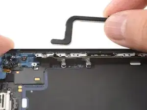
Use your fingers to lay the battery buffer in place.
-
Press down on the buffer for a few seconds to secure it.
-
-
-
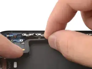
Use a hair dryer or an iOpener to heat the battery buffer until it's warm to the touch. This helps improve the adhesive bond.
-

To reassemble your device, follow these instructions in reverse order.