Introdução
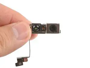
Intermediate logic board disassembly steps.
This can either conclude with the logic board removal or with LiDAR removal.
-
-
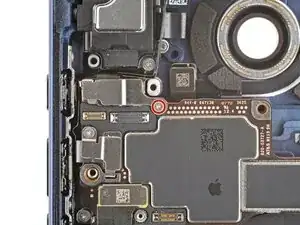
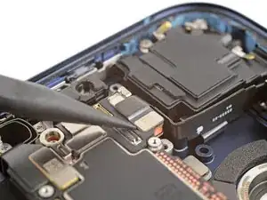
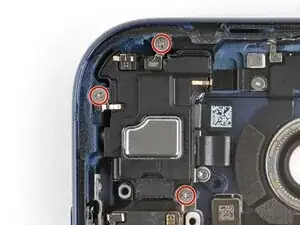
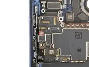
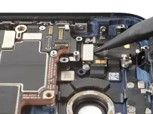
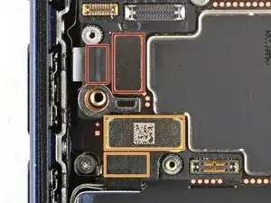
Use a tri-point Y000 screwdriver to remove the 1.0 mm‑long screw securing the front camera connector cover.
-
-
-
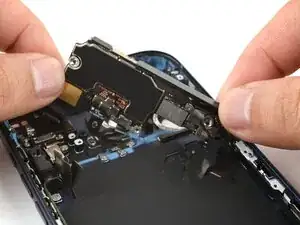
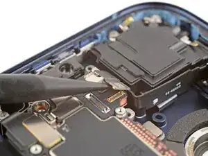
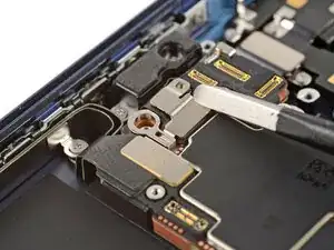
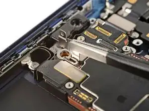
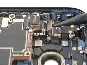
Use the point of a spudger to pry up and disconnect the two front camera connectors (one's under the other) from the logic board.
-
-
-
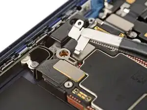
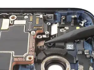
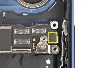
Use a tri-point Y000 screwdriver to remove the 1.0 mm‑long screw securing the button connector cover.
-
-
-
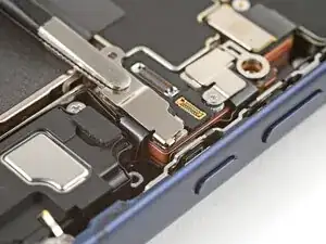
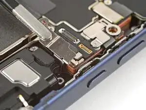
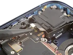
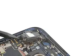
Use the point of a spudger to pry up and disconnect the two press connectors along the top edge of the logic board.
-
-
-
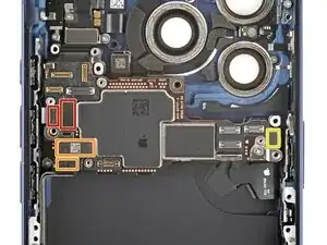
Use the point of a spudger to pry up and disconnect five press connectors on the logic board:
-
Two button board connectors (one's underneath the other)
-
Two USB-C port assembly connectors (one's underneath the other)
-
One power button connector
-
-
-
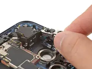
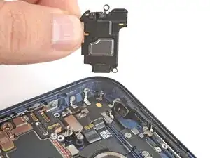
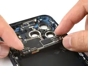
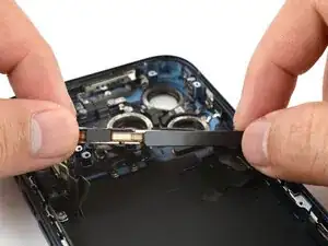
Use your fingers to carefully tilt the bottom left corner of the logic board up until it stands vertical.
-

To reassemble your device, follow these instructions in reverse order.