Introdução
Ferramentas
-
-
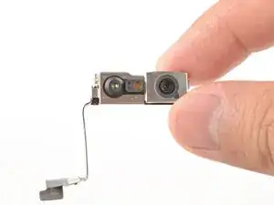
Place the front camera assembly in its recess and carefully guide its cables into the groove.
-
-
-
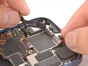
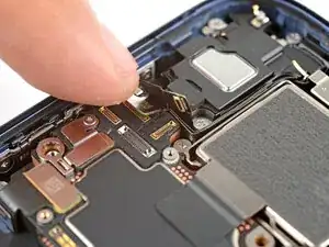
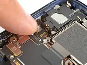
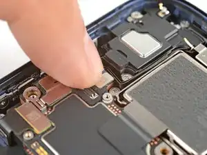
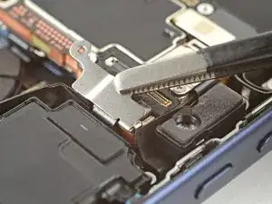
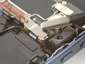
Use your fingers to carefully align and press the two front camera assembly press connectors onto the logic board.
-
-
-
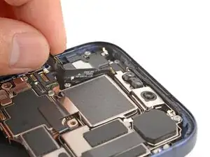
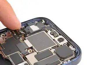
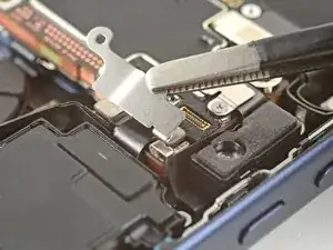
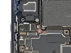
Use a tri-point Y000 screwdriver to install the 1.0 mm‑long screw to secure the front camera connector cover.
-
Conclusão
To reassemble your device, follow these instructions in reverse order.