Introdução
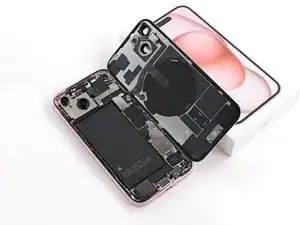
Use this guide to remove or replace the logic board in an iPhone 15.
You'll need replacement back glass and screen adhesive to complete this repair.
If the battery is swollen, take appropriate precautions and follow this guide to replace it.
Due to Apple's parts pairing restrictions, much of your iPhone's functionality depends on the logic board. If you use all genuine parts, run Apple's Repair Assistant (introduced in iOS 18) to avoid any issues. Otherwise, to retain full functionality, you must also replace the following parts with ones that are paired to the replacement logic board:
- Screen (to retain True Tone and Auto-Brightness)
- Front Camera and Sensors (most functionality)
- Battery (to retain battery health data)
Ferramentas
-
-
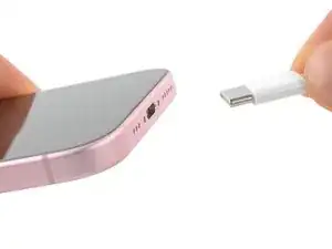
Unplug any cables from your phone.
-
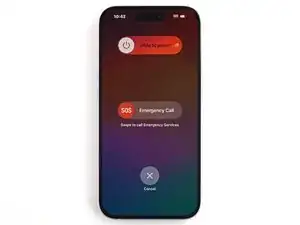
Hold the power and either volume buttons and slide to power off your phone.
-
-
-
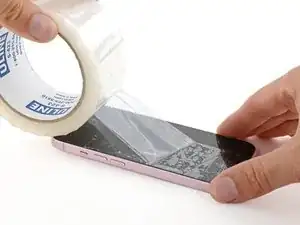
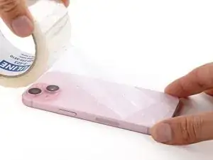
If your screen or back glass is badly cracked, lay overlapping strips of packing tape over the glass to protect yourself and make disassembly easier.
-
-
-
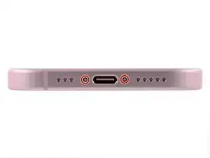
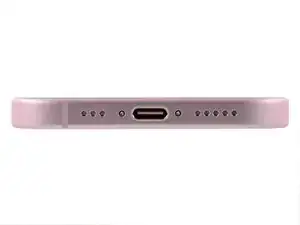
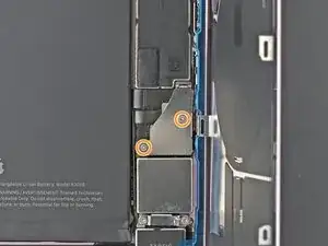
Use a P2 pentalobe driver to remove the two 7.7 mm-long screws on either side of the charging port.
-
-
-
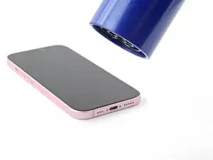
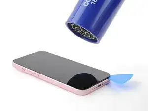
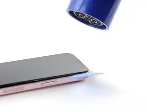
Use a hair dryer or heat gun to heat the bottom edge of the screen until it's hot to the touch.
-
-
-
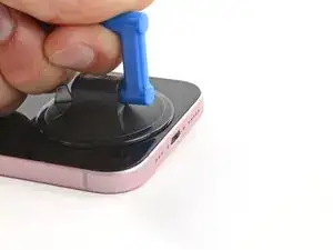
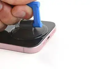
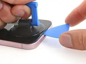
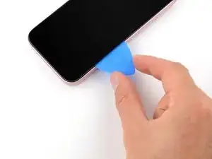
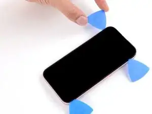
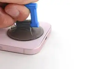
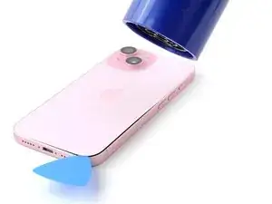
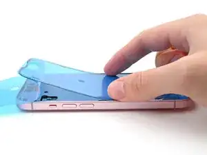
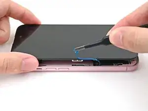
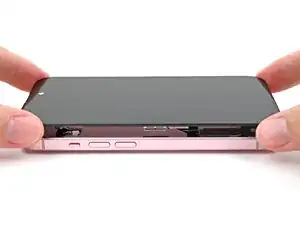
Apply a suction handle to the bottom edge of the screen.
-
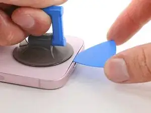
Pull up on the handle with a strong, steady force to create a gap between the screen and the frame.
-
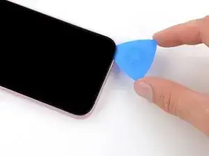
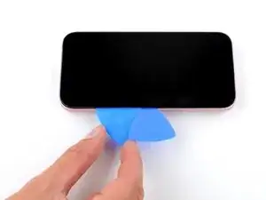
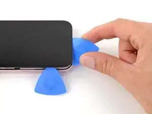
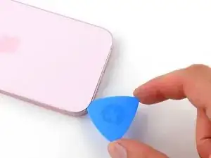
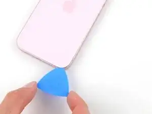
Insert the tip of an opening pick into the gap.
-
-
-
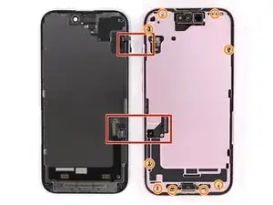
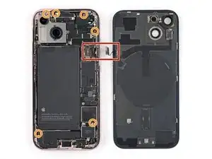
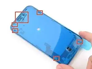
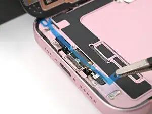
There are two delicate cables connecting the screen to the phone, one just above the mute switch, and the other about halfway between the volume down button and the bottom of the phone.
-
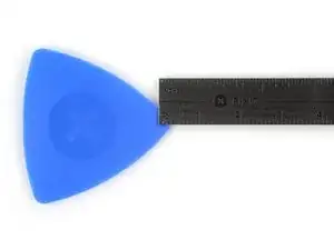
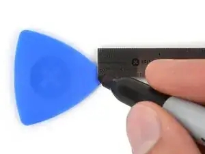
There are multiple spring contacts around the perimeter of the phone. Be extra careful not to insert your pick deeper than suggested in these locations to avoid bending the contacts.
-
-
-
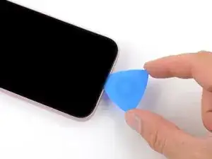
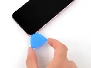
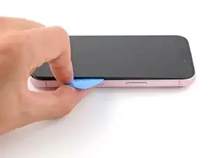
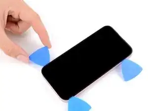
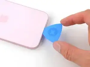
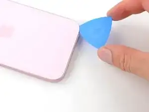
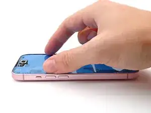
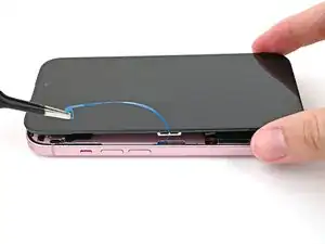
Slide your pick back and forth along the bottom edge to separate the adhesive.
-
Leave your pick inserted in the bottom right corner to prevent the adhesive from re-sealing.
-
-
-
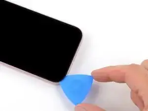
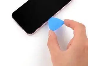
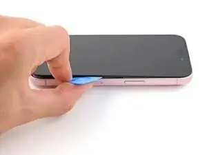
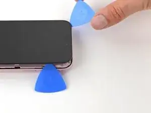
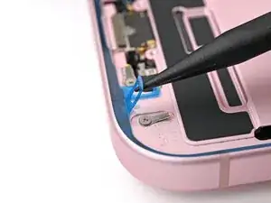
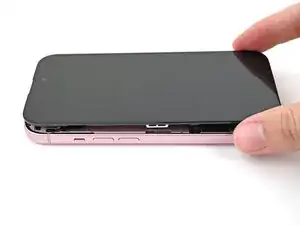
Slide your pick around the bottom right corner of the screen and toward the power button until you feel a hard stop at a clip securing the screen.
-
Rotate your pick so the flat edge is under the screen.
-
-
-
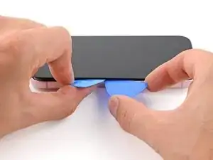
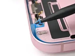
Hold the pick with one hand and twist it to increase the gap between the screen and the frame and release the right clip.
-
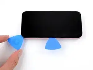
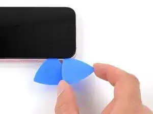
Insert a second opening pick to the right of the first one.
-
-
-
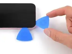
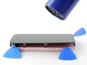
Slide the first pick back to the bottom right corner of the screen.
-
Slide the second pick to the top right corner of the screen to separate the adhesive.
-
Leave these picks inserted to prevent the adhesive from resealing.
-
-
-
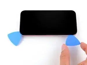
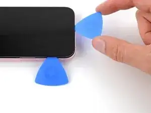
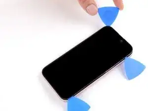
Insert a third opening pick in the top right corner, just above the previous pick.
-
Slide your pick around the top right corner and along the top edge until you feel it stop against the top left screen clip.
-
-
-
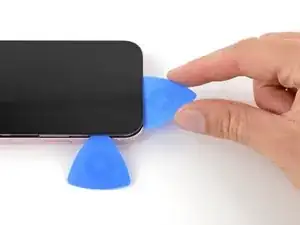
Rotate your pick so its flat edge is under the screen.
-
Twist your pick to release the top left screen clip.
-
Slide your pick to the top left corner.
-
-
-
Slide your pick around the top left corner of the screen and along the left edge to release the clips and separate the adhesive securing it.
-
-
-
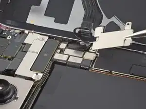
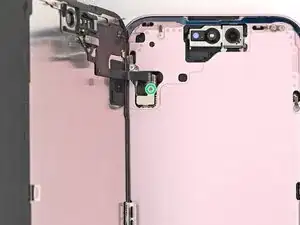
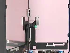
Use a tri-point Y000 driver to remove the 0.9 mm-long screw securing the front sensor connector cover.
-
-
-
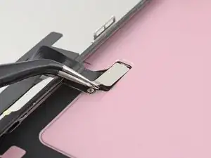
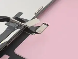
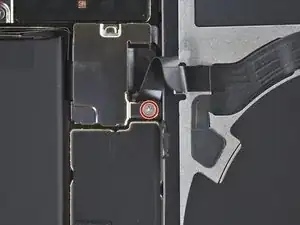
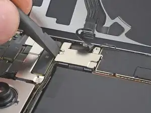
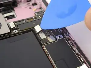
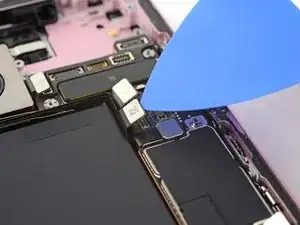
Use your tri-point Y000 driver to remove the 0.9 mm‑long screw securing the screen connector cover.
-
-
-
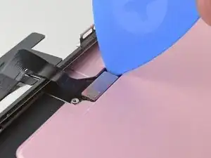
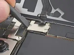
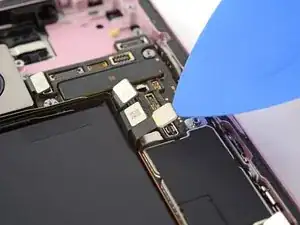
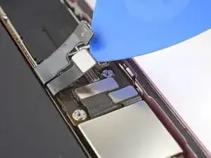
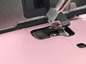
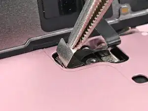
Use tweezers to lift the cover and unlatch it from its hook on the logic board.
-
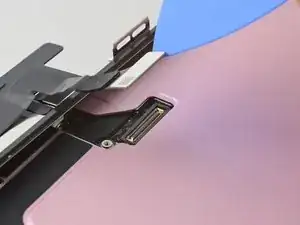
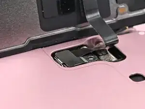
Remove the cover.
-
-
-
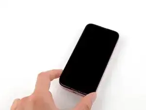
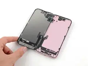
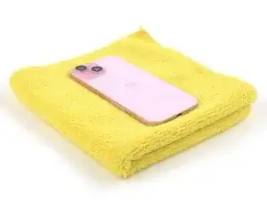
Flip your phone over and lay it on a soft surface, such as a microfiber cloth, to protect its internals as you work.
-
-
-
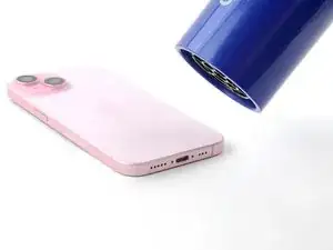
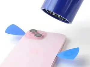
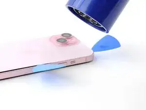
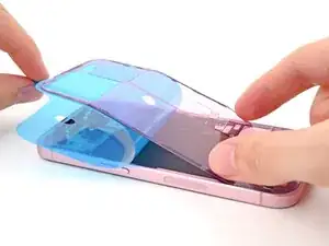
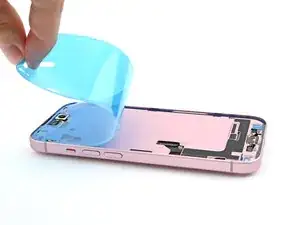
Use a hair dryer or heat gun to heat the bottom edge of the back glass until it's hot to the touch.
-
-
-
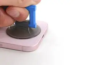
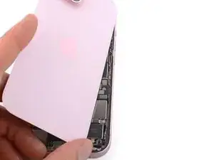
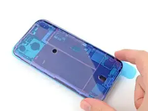
Apply a suction handle to the bottom edge of the back glass.
-
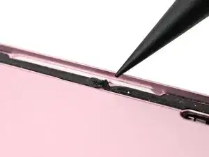
Pull up on the handle with a strong, steady force to create a gap between the back glass and the frame.
-
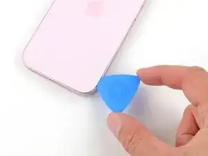
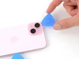
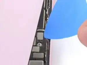
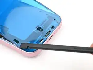
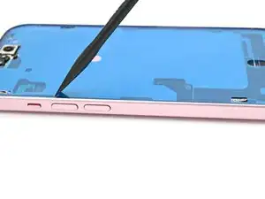
Insert the tip of an opening pick into the gap.
-
-
-
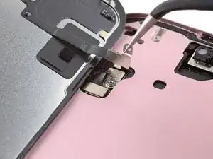
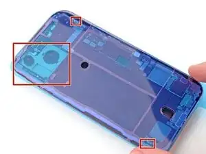
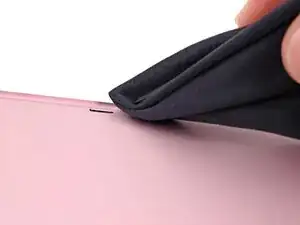
There's a delicate cable connecting the back glass to the phone, right next to the volume down button. Don't insert your pick here to avoid slicing the cable.
-
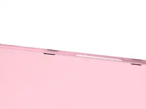
There are multiple spring contacts around the perimeter of the phone. Be extra careful not to insert your pick deeper than suggested in each step to avoid bending these contacts.
-
-
-
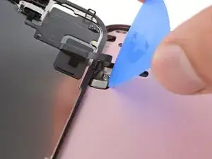
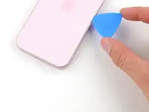
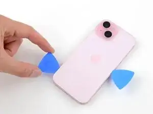
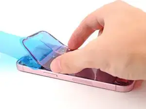
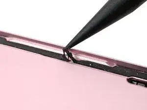
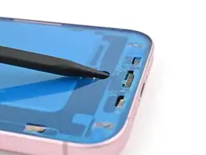
Slide your pick back and forth along the bottom edge to separate the adhesive.
-
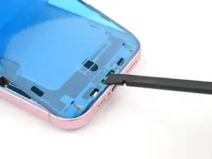
Leave your pick inserted in the bottom right corner to prevent the adhesive from re-sealing.
-
-
-
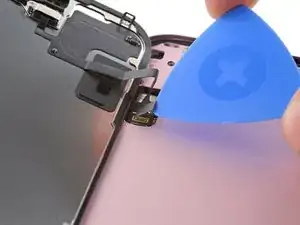
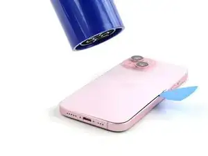
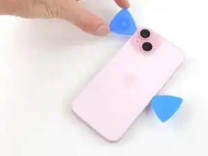
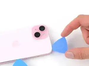
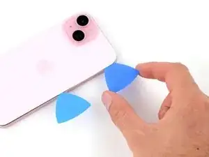
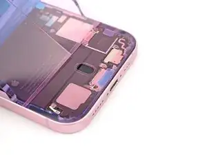
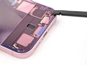
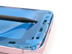
Rotate your pick around the bottom right corner and slide it to the volume down button or until you feel a hard stop at a large clip securing the back glass.
-
Leave this pick inserted to prevent the adhesive from resealing.
-
-
-
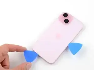
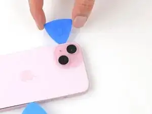
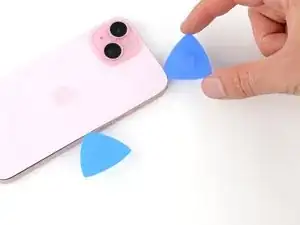
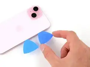
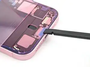
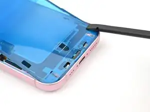
Insert a second opening pick at the bottom edge.
-
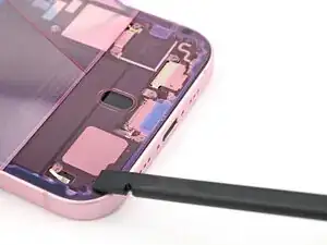
Rotate the second pick around the bottom left corner.
-
Slide this pick up to the top left corner to separate the adhesive.
-
Leave this pick inserted to prevent the adhesive from resealing.
-
-
-
Rotate your second opening pick around the top left corner and slide it to the top right corner to separate the adhesive.
-
Leave this pick in place to prevent the adhesive from resealing.
-
-
-
Rotate the second opening pick around the top right corner and slide it to the volume up button to separate the adhesive.
-
-
-
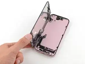
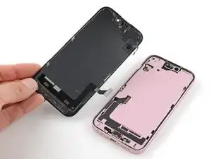
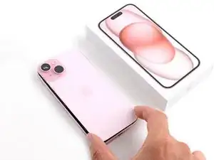
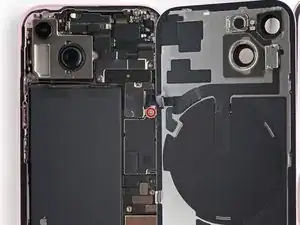
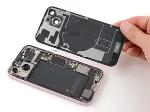
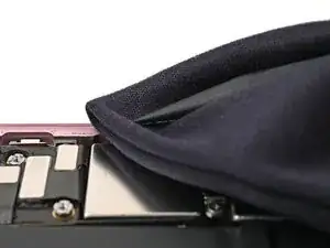
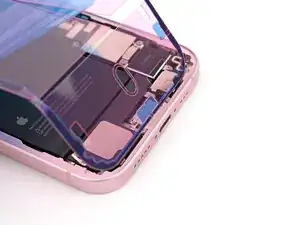
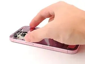
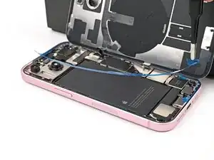
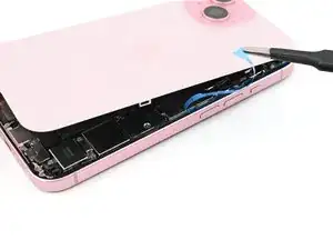
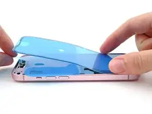
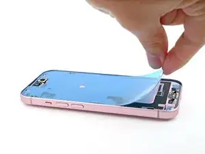
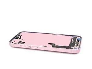
Gently lift and swing open the back glass to the right of the phone.
-
Rest the back glass against a raised surface so it doesn't strain the cable.
-
-
-
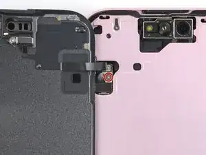
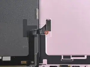
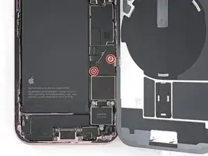
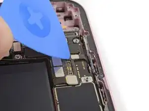
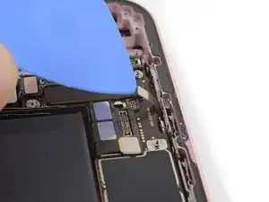
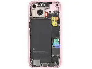
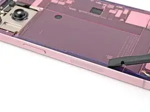
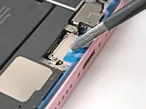
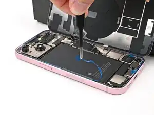
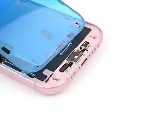
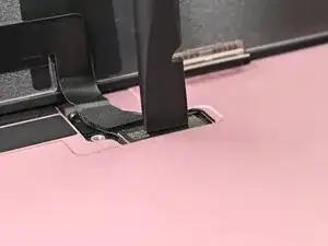
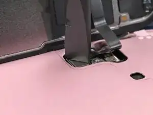
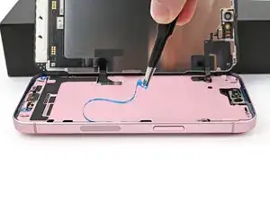
Use a tri-point Y000 driver to remove the two 1.3 mm-long screws securing the lower connector cover.
-
-
-
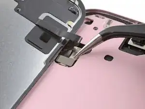
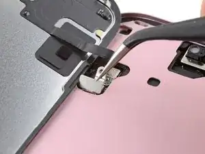
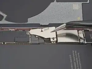
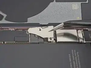
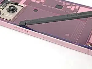
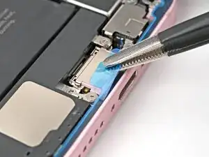
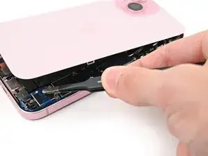
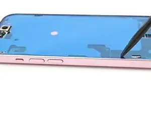
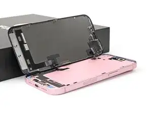
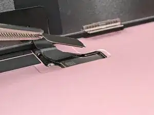
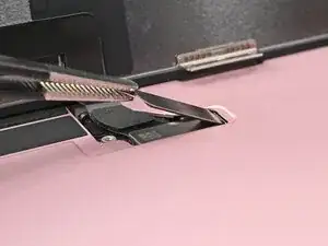
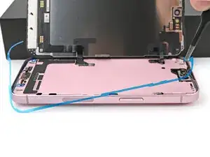
Hold the back glass upright with one hand and rotate it just enough to reveal the battery press connector just below the volume buttons.
-
Use the tip of an opening pick to pry up and disconnect the battery press connector from the logic board.
-
-
-
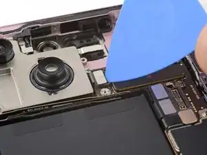
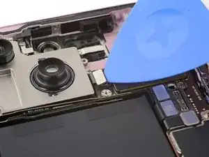
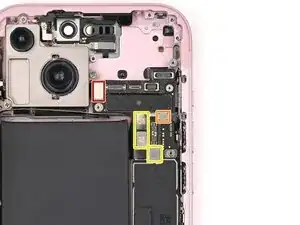
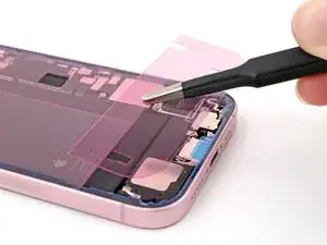
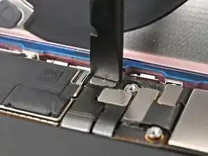
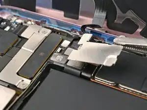
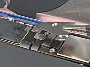
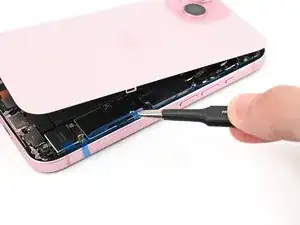
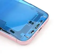
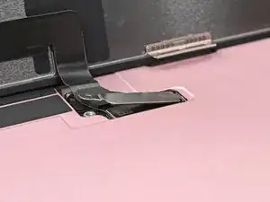
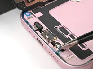
Use your tri-point Y000 driver to remove the 0.9 mm-long screw securing the middle connector cover.
-
-
-
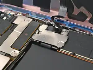
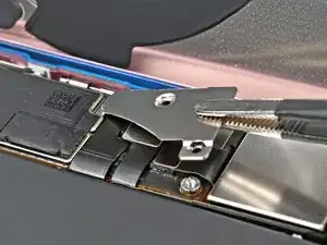
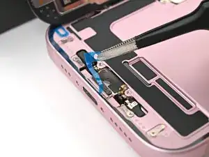
Use the flat end of a spudger or your finger to push the cover toward the bottom of the phone and unclip its top edge.
-
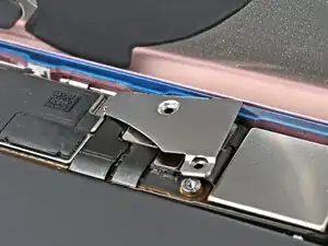
Remove the cover.
-
-
-
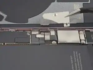
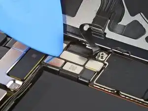
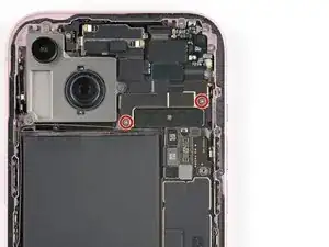
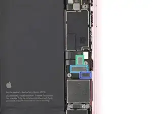
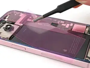
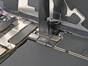
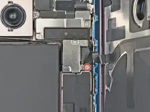
Use your tri-point Y000 driver to remove the two 1.3 mm‑long screws securing the upper connector cover.
-
Remove the cover.
-
-
-
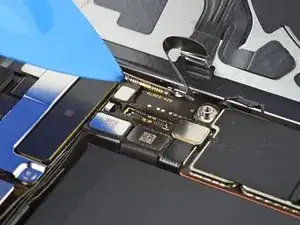
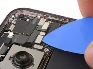
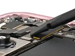
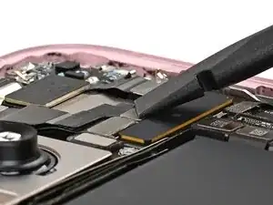
Use the tip of an opening pick to pry up and disconnect the antenna, front sensors, and front camera press connectors (three connectors in total).
-
-
-
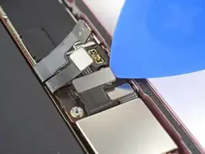
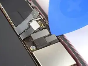
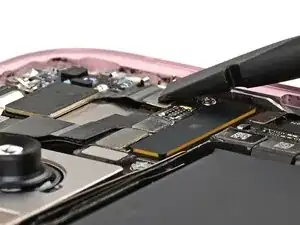
Use the tip of an opening pick to pry up and disconnect the earpiece speaker press connector.
-
-
-
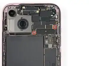
Use a Phillips #000 driver to remove the five screws securing the earpiece speaker:
-
Two 1.1 mm‑long screws
-
Three 1.6 mm‑long screws
-
-
-
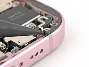
Use the tip of an opening pick to pry up and disconnect the volume buttons press connector.
-
-
-
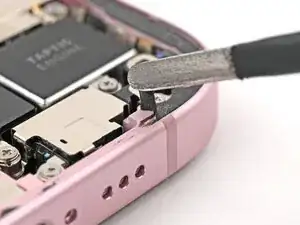
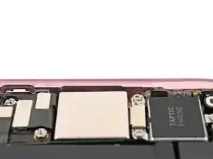
Disconnect the eSIM, Taptic Engine, and charging port press connectors (three connectors in total).
-
-
-
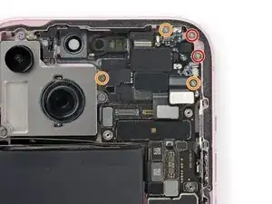
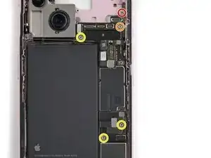
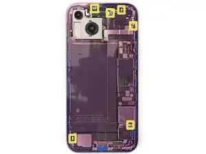
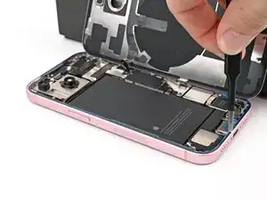
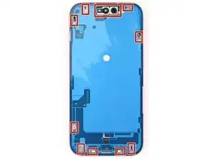
Use your standoff driver to remove the five standoff screws securing the logic board:
-
One 2.9 mm‑long screw
-
One 3.9 mm‑long screw
-
Three 3.5 mm‑long screws
-
-
-
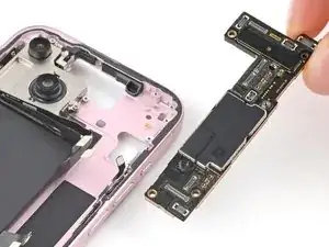
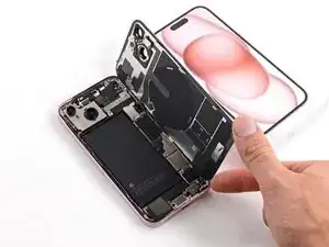
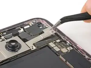
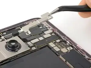
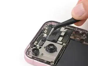
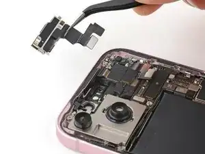
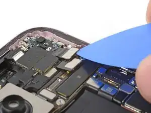
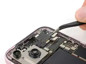
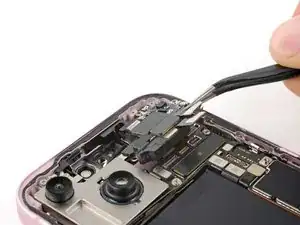
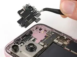
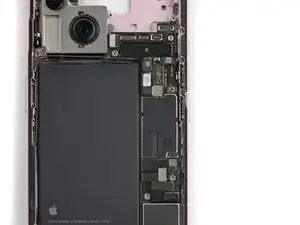
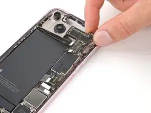
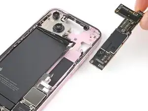
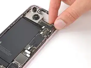
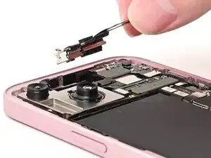
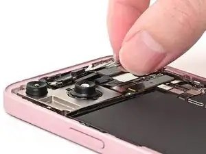
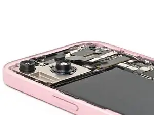
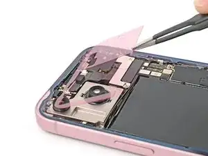
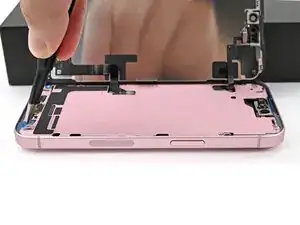
Grip the top edge of the logic board and gently pull it out from under the cables.
-
Remove the logic board.
-
-
-
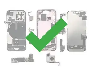
Congratulations on completing disassembly! The remaining steps will show you how to reassemble your device.
-
-
-
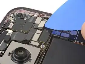
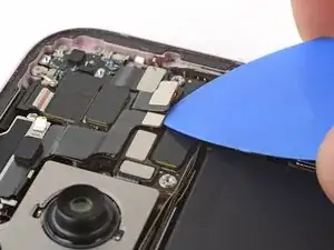
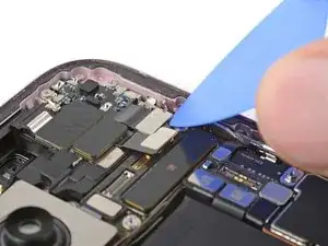
Slide the logic board into its slot in the frame, making sure the nine press connectors are above the logic board.
-
-
-
Use your standoff driver to install the five standoff screws securing the logic board:
-
One 2.9 mm‑long screw
-
One 3.9 mm‑long screw
-
Three 3.5 mm‑long screws
-
-
-
Use your spudger or your fingers to connect the eight press connectors:
-
The power button
-
The volume button
-
The rear cameras and antenna (three connectors in total)
-
The eSIM
-
The Taptic Engine
-
The charging port
-
-
-
Align the gasket on the earpiece speaker with its sound channel.
-
Press the earpiece speaker onto the frame so it lies flat.
-
-
-
Use a Phillips #000 driver to install the five screws securing the earpiece speaker:
-
Two 1.1 mm‑long screws
-
Three 1.6 mm‑long screws
-
-
-
Slide the front camera assembly into its recess in the frame.
-
Set the assembly down so it lies flat.
-
-
-
Use the flat end of a spudger or your finger to connect the front camera and earpiece speaker press connectors.
-
If the iPhone has a mmWave antenna, connect it as well.
-
-
-
Place the cover over the logic board and align its screw holes.
-
Use your tri-point Y000 driver to install the two 1.3 mm‑long screws securing the upper connector cover.
-
-
-
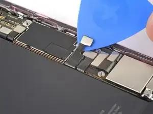
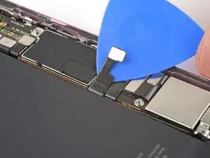
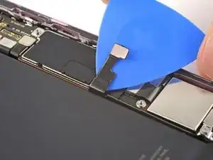
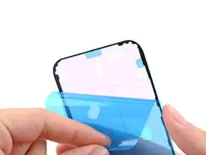
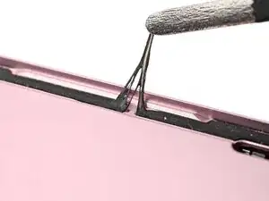
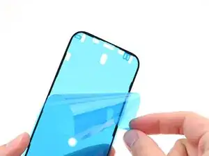
Use the pointed end of a spudger to press and roll the adhesive until you can grip it with a pair of tweezers.
-
Use the tweezers to pull the adhesive off of the phone.
-
-
-
Wrap a microfiber or lint-free cloth around the pointed end of a spudger and apply a few drops of high-concentration (greater than 90%) isopropyl alcohol to the cloth.
-
Wipe in one direction along the perimeter of the frame to clean the adhesive residue.
-
Wait a few minutes before proceeding to make sure any excess alcohol has evaporated.
-
-
-
Lay the adhesive next to the phone and use features like cutouts for spring contacts and the rear camera to make sure the adhesive is oriented correctly.
-
-
-
Use the pull tab to begin peeling the back liner off the adhesive starting from the bottom, but don't remove the liner all the way.
-
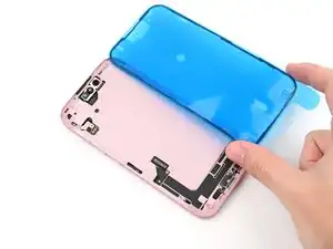
Hold the liner out of the way and align the adhesive with the bottom edge of the iPhone.
-
Lay the bottom edge of the adhesive into its recess in the frame, making sure the iPhone's spring contacts are aligned with their cutouts in the liner.
-
-
-
When the adhesive is aligned, use the flat end of a spudger or your finger to press it down firmly along the bottom edge.
-
-
-
Continue peeling the back liner off of the adhesive while pressing the adhesive into place along the edges of the iPhone's frame.
-
-
-
Make sure the liner is aligned properly by checking that all spring contacts and the rear camera are in their cutouts. If they aren't, remove the adhesive and start over with a new sheet.
-
Use the flat end of a spudger to press the adhesive into place around the perimeter of the frame.
-
-
-
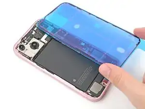
Prop up the back glass along the right edge of the iPhone, using a box or similar sturdy object to support the screen.
-
Use the flat end of a spudger or your finger to connect the wireless charging coil press connector, then the battery press connector.
-
-
-
Place the middle connector cover over the wireless charging coil press connector so it slightly overhangs the slot on the logic board for the bottom clip.
-
-
-
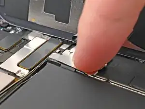
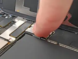
Use your finger to press the cover down on the logic board.
-
While pressing it down, slide the cover upward so both metal clips slot into their spots in the logic board.
-
-
-
Use tweezers to hook the top of the lower connector cover into its slot on the logic board.
-
Lay the lower connector cover over the press connectors.
-
-
-
Use a tri-point Y000 screwdriver to install the 0.9 mm‑long screw securing the middle connector cover.
-
Use a tri-point Y000 screwdriver to install the two 1.3 mm‑long screws securing the lower connector cover.
-
-
-
Use tweezers or your fingers to separate the pull tabs at the bottom of the frame, near the charging port.
-
-
-
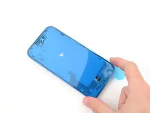
Hold the back glass over the phone without letting it touch the adhesive, so you can access the remaining liners along the right edge of the phone.
-
Use a pair of tweezers or your fingers to remove the remaing liners along the right edge of the phone.
-
-
-
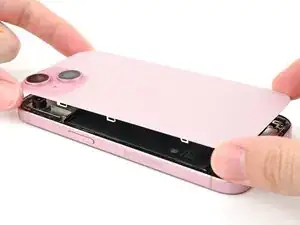
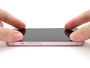
Lay the back glass straight down onto the frame and press until the clips engage.
-
Press around the perimeter of the back glass to engage all the clips.
-
-
-
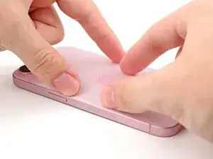
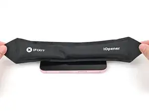
To help the adhesive bond, apply heat to the edges of the back glass using an iOpener, hair dryer, or heat gun until it's hot to the touch.
-
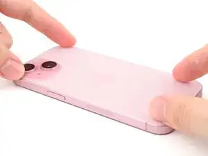
Firmly press around the perimeter of the back glass.
-
-
-
Use a spudger to push the screen adhesive up until you can grab it with a pair of tweezers.
-
Use a pair of tweezers, or your fingers, to remove the adhesive around the entire perimeter of the iPhone.
-
-
-
Wrap a microfiber or lint-free cloth around the pointed end of a spudger and apply a few drops of high-concentration (greater than 90%) isopropyl alcohol to the cloth.
-
Wipe in one direction along the perimeter of the frame to clean the adhesive residue.
-
Wait a few minutes before proceeding to make sure any excess alcohol has evaporated.
-
-
-
Lay the adhesive next to the phone and use features like cutouts for spring contacts and the front‑facing camera to make sure the adhesive is oriented correctly.
-
-
-
Use the pull tab to begin peeling the back liner off of the adhesive starting from the bottom, but do not remove the liner all the way.
-
While holding the back liner out of the way, carefully align the exposed edge of the adhesive to the bottom edge of the iPhone's frame.
-
-
-
When the adhesive is aligned, use the flat end of a spudger, or your finger, to press it down firmly along the bottom edge.
-
-
-
Continue peeling the back liner off of the adhesive while pressing the adhesive into place along the edges of the iPhone's frame.
-
-
-
Make sure the liner is aligned properly by checking that all spring contacts and the front-facing camera are in their cutouts. If they aren't, remove the adhesive and start over with a new sheet.
-
Use the flat end of a spudger to press the adhesive firmly into place all around the iPhone.
-
-
-
Insert the point of a spudger under the top liner's hole at the bottom of the frame.
-
Pry up to separate the liner from the frame—enough to grip it with your fingers.
-
-
-
Prop the screen up along the left edge of the iPhone frame, using a box or similar sturdy object to support the screen.
-
-
-
Use the flat end of a spudger or your finger to connect the screen and front sensor press connectors.
-
-
-
Insert the top of the screen connector cover into its slot in the frame and lay it over the press connector.
-
-
-
Insert the front sensor connector cover into its slot in the frame at a 90‑degree angle vertically.
-
Lay the cover over the press connector.
-
-
-
Use a tri-point Y000 driver to install the two 0.9 mm‑long screws securing the front sensor connector and screen connector covers.
-
-
-
Use a spudger, or your fingers, to separate the pull tabs at the bottom right corner of the frame.
-
-
-
Without letting the screen touch the adhesive, hold the screen over the phone so you can access the final liner along the left edge of the phone.
-
Use a pair of tweezers or your fingers to remove the final liner along the left edge of the phone.
-
-
-
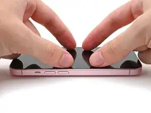
Lay the screen straight down onto the frame and press until the clips engage.
-
Press around the perimeter of the screen to engage all clips.
-
-
-
To help the adhesive bond, apply heat to the edges of the screen using an iOpener, hair dryer, or heat gun until it's hot to the touch.
-
If you have screen vise clamps, use them to strengthen the bond of your new adhesive. If not, keep reading for more ways to secure the screen.
-
-
-
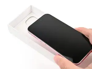
If you have the box your iPhone came in, take the lid and place it on a flat surface.
-
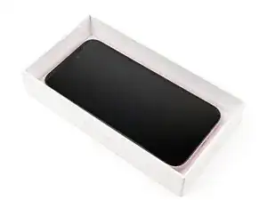
Place your iPhone screen-side-up in the lid of your box with the camera bump in its recess.
-
Find something close to the size of your iPhone, but taller than the sides of the box. Stack it on top of the iPhone, followed by a few heavy objects.
-
Leave the objects in place for at least thirty minutes. The lighter the objects, the longer they should be left. Ideally, leave them stacked overnight.
-
-
-
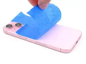
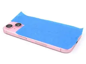
Place the iPhone screen-side-down on a soft, flat surface.
-
Apply tape to the back glass to protect its finish.
-
-
-
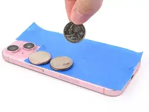
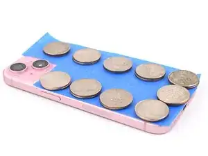
Place evenly spaced layers of coins or similarly thick objects on the tape along the edges of the back glass.
-
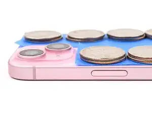
Stack them to a consistent height taller than the camera bump.
-
-
-
Stack multiple books or other heavy objects on your iPhone.
-
Leave the objects in place for at least thirty minutes. The lighter the objects, the longer they should be left. Ideally, leave them stacked overnight.
-
-
-
Use a P2 pentalobe driver to install the two 7.7 mm‑long screws on either side of the charging port.
-


Take your e-waste to an R2 or e-Stewards certified recycler.
Repair didn’t go as planned? Try some basic troubleshooting, or ask our Answers community for help.

Um comentário
You can remove the logic board without removing the screen if you carefully flip the logic board over during removal.