Introdução
Is your Zelotes C-18 mouse no longer tracking movement smoothly or failing to respond altogether? This guide will walk you through how to safely remove and replace the laser sensor in your mouse to restore proper performance.
The laser sensor is responsible for detecting surface movement and sending that data to your computer. Over time, it can fail due to dust buildup, internal wear, or electrical issues. Replacing it can help bring your mouse back to full accuracy and responsiveness.
Be careful when working inside the mouse, the internal components, including the circuit board and sensor connections, are delicate and can be easily damaged if handled roughly.
Before starting, unplug the mouse from your computer and make sure you’re working on a clean, static-free surface.
Estimated time would be around 30-35 minutes
-
-
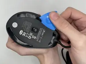
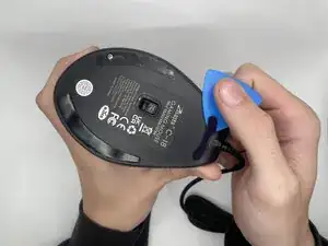
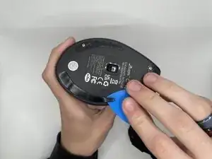
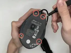
Use an opening pick to gently pry off the mouse feet and stickers on the bottom of the mouse to expose four hidden screws.
-
-
-
Using a Phillips #0 screwdriver to remove the four 9 mm-long screws on the bottom of the mouse.
-
-
-
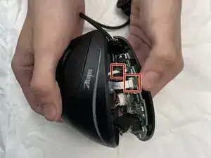
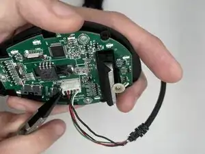
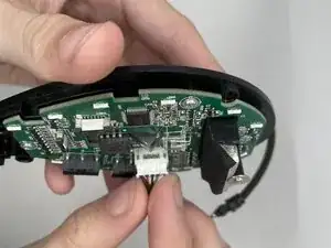
Using a spudger, carefully lift the locking tab by gently alternating pressure on each side until it’s in the unlocked position
-
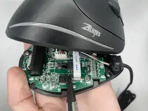
Detach the ribbon cables by gently pulling them straight (perpendicularly) away from the motherboard.
-
-
-
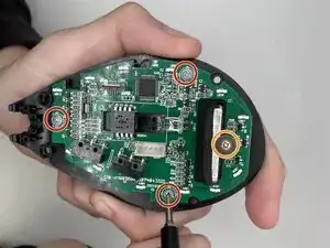
Using a Phillips #0 screwdriver, remove all four screws securing the motherboard:
-
Three 5 mm-long screws
-
One 7 mm-long screw
-
-
-
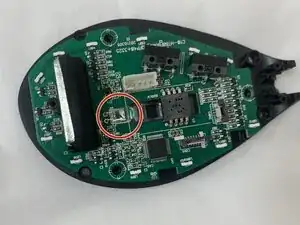
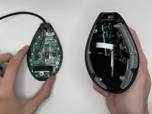
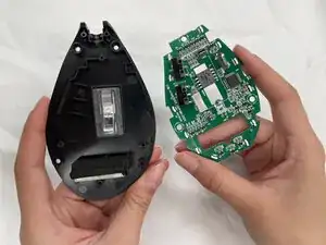
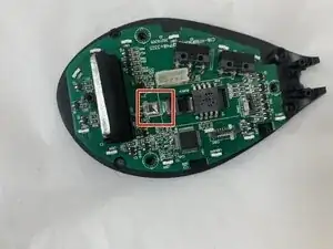
Flip the motherboard over to expose the solder joints holding the LED in place.
-
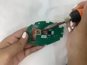
Use a soldering iron carefully desolder the LED.
-
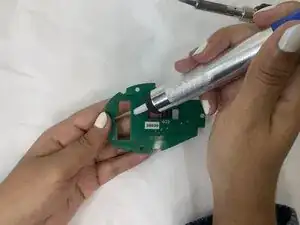
Use the desoldering pump to suck up and remove the solder, gently push the old sensor out of the board.
-
To reassemble your device, follow the above steps in reverse order.
Take your e-waste to an R2 or e-Stewards certified recycler.
Repair didn’t go as planned? Try some basic troubleshooting or ask our Answers community for help.