Introdução
This Guide is on how to upgrade your SteelSeries Arctis 7 to a USB-C port.
The Datapins are preserved so the headset still retains all of its functionality and can be connected to the PC via USB.
Note it will be somewhat destructive to your Headset, as the Port needs to be widened and some place has to be carved out of the Headset to fit the larger USB-C Port.
This has already been done by another user named Kireobat, though I use another approach: SteelSeries Arctis 1/7 micro USB port Replaced with USB C port.
Ferramentas
Peças
-
-
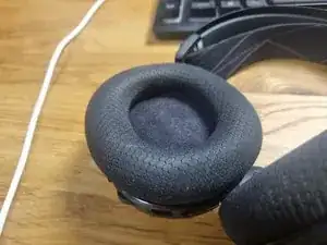
Remove Ear Cushions
-
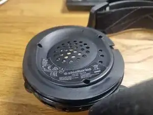
Use the Torx T6H Bit to remove the screws
-
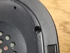
Gently lift the speaker side. Watch out for the Cables
-
-
-
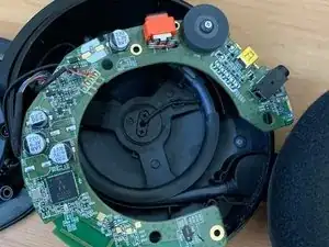
Take out the Circuit Board
-
Pushing on the Volume knob helps to get it out
-
Source of the image: https://www.reddit.com/r/steelseries/com...
-
-
-
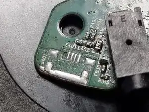
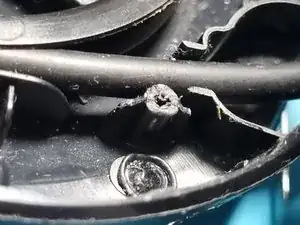
Remove and clean the Micro USB solder spot
-
My Micro USB has been ripped out. That's why I'm missing my pad
-
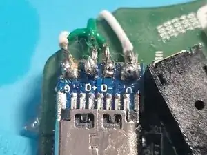
The pins are From left to right:
-
1. VCC
-
2. D-
-
3. D+
-
4. ID
-
5. GND
-
-
-
Add a 5.1 kOhm Resistor on between R1 and GND to configure the USB-C as a slave
-
Cover the open Pads with Kapton Tape
-
-
-
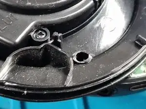
Trim the plastic from the bottom screw hole on both the top and bottom halves of the case to make place for the port.
-
Note this may impact the robustness of your device. I did not notice any drawbacks
-
-
-
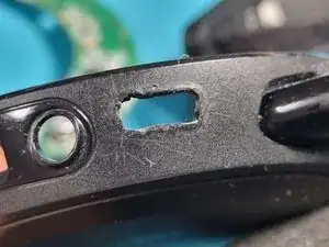
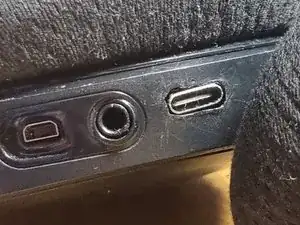
Enlarge the micro USB cutout with a soldering iron
-
Lowering the temperature of your soldering iron gives you better control when enlarging the hole
-
-
-
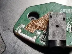
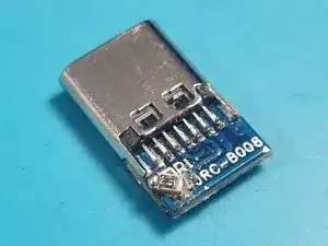
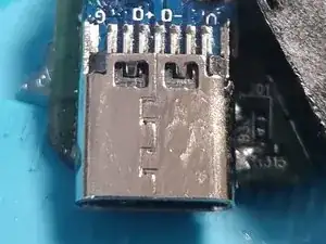
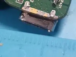
Use isopropyl alcohol to clean the USB-C connector and PCB
-
Position the USB-C board with a 2–2.5 mm overhang from the PCB
-
Preheat the USB-C board using a soldering iron or a heat gun if available. It helps in soldering as it has a large thermal mass
-
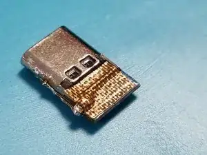
Melt solder on the GND pads. Ensure they are fully covered and thoroughly heated
-
Place the board on the GND pads. Use additional heat
-
-
-
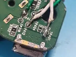
Solder Jumper cables to the following breakout pins
-
Solder Connections:
-
TP401 for V
-
TP403 for D+
-
TP404 for D-
-
TP412 for GND
-
Ensure each connection is secure, has proper contact and free of shorts
-
-
-
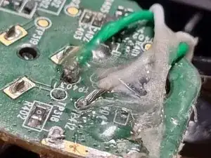
Solder the cables to the corresponding pads on the USB-C board
-
(Optional): Add hot glue to the connections on both sides for extra stability
-
-
-
Position the board in the case. Push the ports into the cutouts
-
Adjust until screw holes on the case match those on the PCB
-
Close the headset and fasten the srews
-
CONGRATS !! You made it :D
-
To reassemble your device, follow these instructions in reverse order.

4 comentários
Hey does this provide data and charging or only charging?
Yes it does provide data and charging as you also solder the datapins to the USB C port.
So it is being recognized by the software.
I tried to attach a USB-C connector to the dongle, and the D+ line came off. Do you know which pin is the D+ breakout pin on the dongle?
I don't understand you completely. But as far as I understood you, you have the USB-C Board, there you tried to solder the cable to a pin on that USB-C board, but it then the D+ pad ripped off?
If so, I would just order a new one, as they are quite cheap.
If you really want to use that board, I would suggest using a multimeter in continuity mode, to probe the places where the data line goes to. Alternatively, you can also look at a USB-C schematic to find the D+ pin on the board.
Best of luck in your repair! Hope it turns out to be a success!