Introdução
Ferramentas
-
-
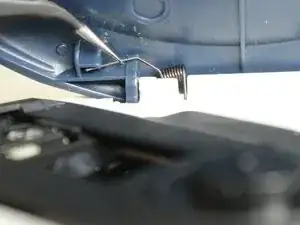
Grip the thin end of each spring using a pair of tweezers, slide it out of the lid notch, then press down on the main coil to release and remove it.
-
-
-
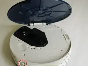
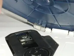
Insert the metal spudger in the crevice between the blue lid and the white body of the Walkman.
-
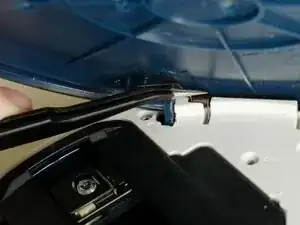
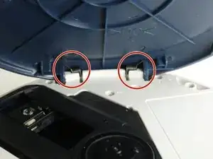
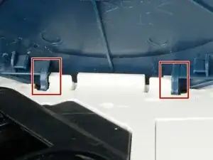
There is a notch where the lid is held under to stay in place. With the spudger, push the blue lid portion down and out.
-
Repeat the same tactic on the other side. The other side should become easier to pop off.
-
Remove the lid.
-
-
-
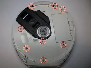
Remove the eight 6.1 mm screws using a Phillips #00 screwdriver.
-
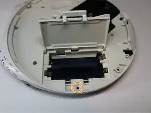
Open the battery cover to reveal the last screw.
-
Remove the ninth 6.1 mm screw using a Phillips #00 screwdriver.
-
-
-
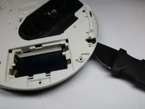
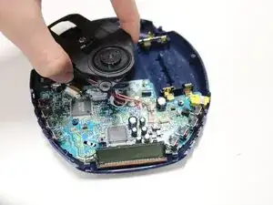
Insert a Jimmy into the seam between the upper and lower cases and pry apart.
-
Avoid initially prying near buttons, or the laser assembly.
-
Pry until the there is an audible click. The halves should visibly separate roughly 1/4 in.
-
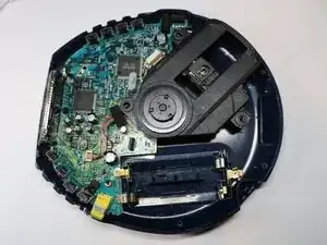
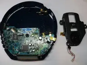
Work around the seam in a circular path, separating the halves completely.
-
-
-
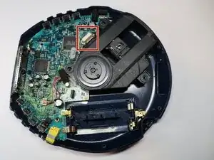
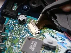
Using tweezers, gently lift the the locking flap on the laser module ribbon connector.
-
Gently remove the ribbon cable from the connector.
-
-
-
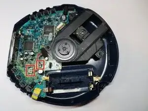
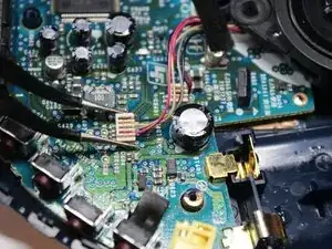
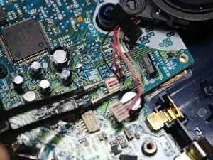
Using tweezers, squeeze the upper half of the four wire connector, and lift straight up to remove the connector.
-
Repeat the step for the two wire connector.
-
To reassemble your device, follow these instructions in reverse order.