Introdução
Ferramentas
-
-
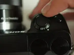
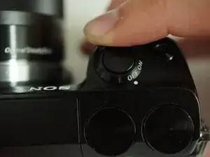
If the camera is on, rotate the power switch on top of the camera counterclockwise to turn the camera off.
-
-
-
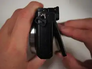
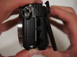
Flip the camera over such that the power switch points down.
-
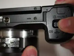
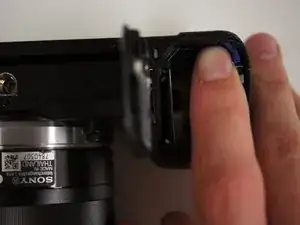
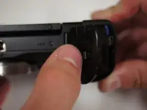
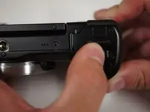
Slide the switch on the bottom of the camera grip towards the lens to open the battery door.
-
-
-
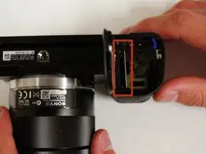
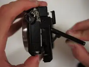
With the battery door open, push the blue lever in the battery compartment to release the battery.
-
-
-
To the left of the battery compartment, the SD card needs to be pushed down slightly with your fingers, which will cause the card to eject.
-
Pull the card out with your fingers.
-
-
-
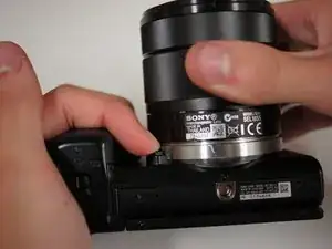
First, turn the camera upside down.
-
Press the button located next to silver lens mount and rotate the lens counterclockwise.
-
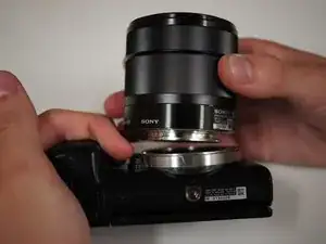
Pull the lens away from the camera body.
-
-
-
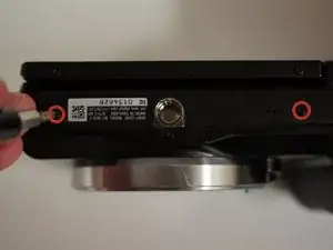
Start by removing the two 5/32" #00 screws on the bottom of the camera using the Phillips #00 screwdriver.
-
-
-
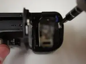
Remove the 5/32" #00 screw at the top of the compartment using the Phillips #00 screwdriver.
-
Remove the two 5/32" #00 screws from inside the compartment using the Phillips #00 screwdriver.
-
-
-
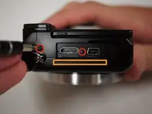
Looking at the left side of the camera, lift open the door that has 'HDMI' written on it.
-
Remove the two visible 5/32" #00 screws using the Phillips #00 screwdriver.
-
-
-
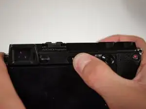
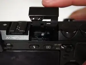
Looking at the back of the camera, press the button with a lightning bolt on it to pop the flash open.
-
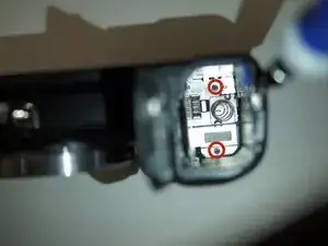
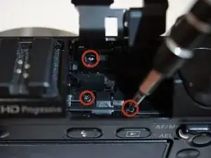
Remove the three 5/32" screws from within the flash compartment using the Phillips #00 screwdriver.
-
Close the flash compartment.
-
-
-
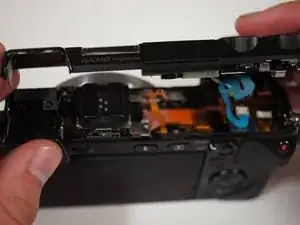
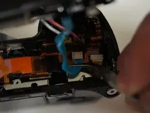
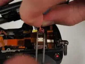
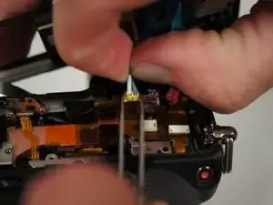
Place the tips of your tweezers on either side of the red jack.
-
Gently pull the red plug out of the jack.
-
Repeat those steps for the yellow jack and plug.
-
Now that the top is free, place it aside for later.
-
-
-
Lift the LCD screen with your fingers such that the screen is bent slightly away from the camera.
-
-
-
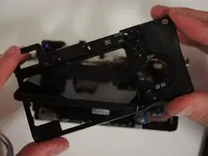
Starting at the bottom, gently pry the back panel away from the body of the camera using your fingers.
-
Once the back panel is free from the body, rotate the camera such that back is facing you and pull the back panel past the screen by rotating it to fit around the screen.
-
Set the back panel aside.
-
-
-
Remove the two 3/32" #00 screws located next to the viewfinder using the Phillips #00 screwdriver.
-
-
-
Use a Phillips #00 screwdriver to remove the two screws from the right side of the camera below the D ring:
-
The 5/32" upper screw
-
The 3/32" lower screw
-
-
-
Remove two more 3/32" #00 screws from the bottom of the camera using the Phillips #00 screwdriver.
-
-
-
Remove two more 3/32" #00 screws from the metal bracket on the left side of the camera using the Phillips #00 screwdriver.
-
-
-
Before pulling off the assembly, fold the rightmost tab of the flexible circuit board away from the metal bracket.
-
-
-
Pull on the D rings on either side of the camera to start removing the assembly.
-
Once the brackets are cleared from black shell, take them off and set them aside.
-
Continue to remove the screen assembly.
-
-
-
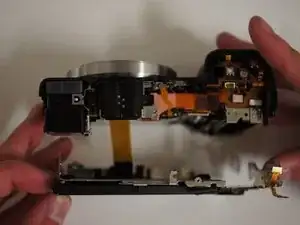
With the camera face down, move the assembly away from you to get a clear view of the wide ribbon cable.
-
Unplug the cable by applying tweezers to the tabs on either side of the plug.
-
Set the LCD assembly aside.
-
-
-
Remove the 5/32" #00 screw next to the back right of the viewfinder using the Phillips #00 screwdriver.
-
-
-
Using the tweezers lift the black piece of tape from the circuit board below the viewfinder.
-
-
-
Use the tweezers to lift the black switch on the white receptacle just below the viewfinder. If properly opened, the ribbon cable will remove with very little force.
-
-
-
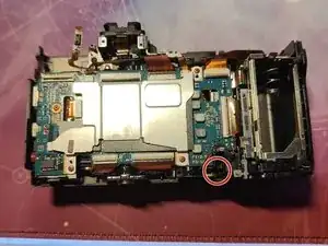
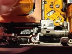
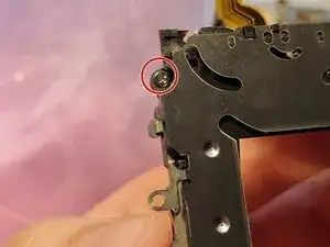
Remove the M1.4 X 3.5 black screw with a JIS 00 screwdriver marked with a red circle.
-
Carefully take the battery door assembly out of the shell, it will have wires to the speaker.
-
Make sure to pay attention not to rip these wires off the board while taking it apart. Once you remove the motherboard it will come with it.
-
-
-
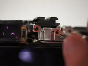
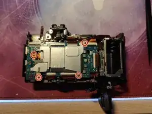
Remove the 4 red M1.4 X 2.5 screws with a JIS 00 screwdriver marked with red circles in Picture 1.
-
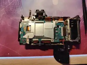
Remove the metal shield.
-
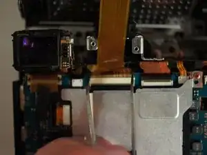
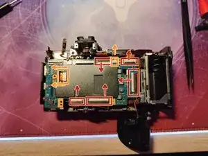
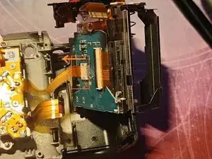
First open the latches on the FPC connectors marked with red rectangles in the direction of the arrows as shown in Picture 3.
-
The FPC connectors marked with orange rectangles don't have locking tabs, you only have to remove them in the direction of the arrows as shown in Picture 3.
-
I suggest removing the one on the left with a pair of tweezers, by putting both of them on the two little tabs and pushing in the direction of the arrows, and the other one (on the right) just hold it with your fingers and pull it in the direction of the arrow.
-
Please don't try to remove the motherboard until you have read the next step.
-
-
-
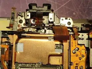
Carefully lift the motherboard from the left side and tilt it to the right, there are still 2 flex cables connected.
-
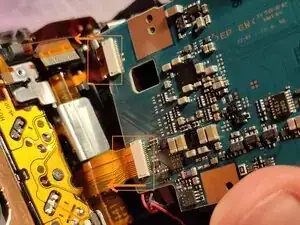
Remove the two flex cables from the motherboard marked with orange rectangles in Picture 1.
-
These flex cables don't have locking tabs, please remove them in the direction of the arrows as shown.
-
During reassembly, please connect these cables first otherwise you are not able to reassemble a fully functioning camera.
-
Remove one black M1.4 x 3.5 screw with a JIS 00 screwdriver marked with a red circle in Picture 3.
-
-
-
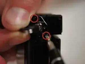
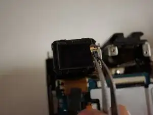
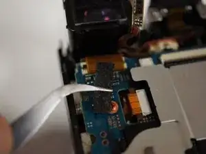
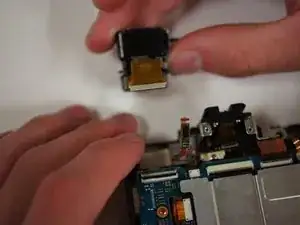
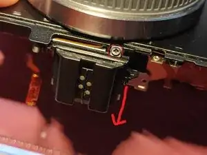
Remove the black M1.4 X 2.0 screw with a JIS 00 screwdriver marked with a red circle in Picture 1.
-
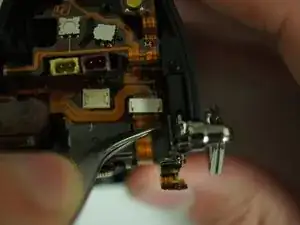
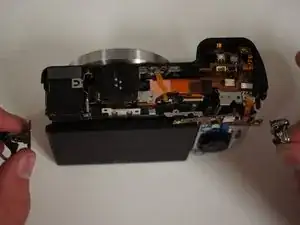
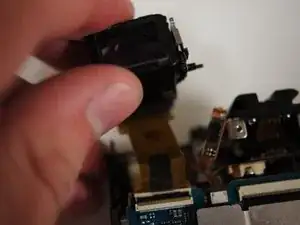
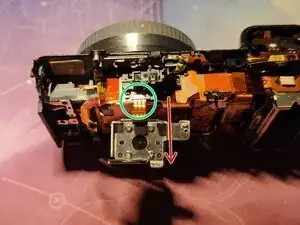
Tilt the hot shoe in the direction of the red arrow as shown in Picture 1, you should end up like you can see in Picture 2.
-
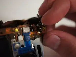
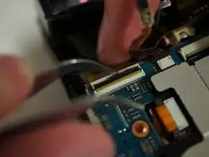
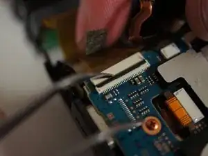
Carefully remove the flex cable (marked with a green circle) from the FPC connector in the direction of the red arrow shown in Picture 2.
-
I recommend grabbing it firmly with two fingers and simply pulling it out.
-
-
-
Gently lift up the sensor flex cables to reveal a screw underneath marked with red circles in Picture 1 and 2.
-
Remove this black M1.4 x 3.5 screw with a JIS 00 screwdriver.
-
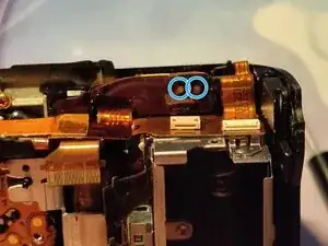
Locate the flex cable shown in Picture 3 and before proceeding to the next step, please make sure you have successfully drained the flash capacitor, otherwise you risk electrocuting yourself.
-
To drain the capacitor I suggest using your multimeter and putting each probe on each draining pad marked with blue circles in Picture 3. Make sure it goes all the way down to ~ 5 volts.
-
-
-
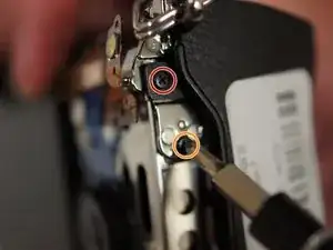
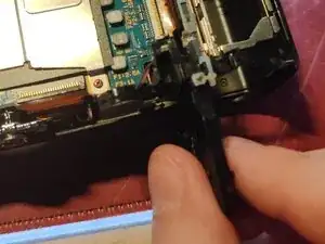
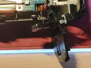
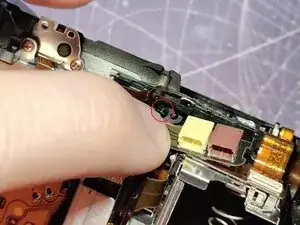
Gently tilt down the flex cable as shown in Picture 1, and locate the screw marked with a red circle.
-
Remove this black M1.4 X 3.5 screw with a JIS 00 screwdriver.
-
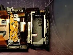
Remove the big bracket containing the plastic door covering the ports on the left.
-
Remove the silver M1.7 X 4.0 (Tapping) screw with a JIS 00 screwdriver marked with a red circle in Picture 2.
-
Carefully lift out the battery compartment assembly, there is still one flex cable without any locking tabs (marked with an orange rectangle in Picture 3) connected.
-
Grab it firmly with your fingers and gently pull it out in the direction of the orange arrow.
-
Put the battery compartment aside.
-
-
-
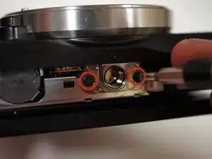
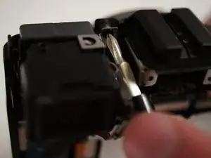
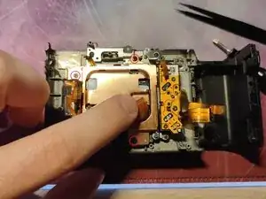
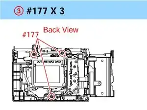
Remove the 3 black M1.7 X 3.5 screws marked with red circles in Picture 1 with a JIS 00 screwdriver.
-
Be careful this remove both the heatsink and the sensor, meaning they will come apart.
-
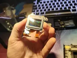
Carefully lift the sensor out, making sure not to lose any adjusting washers which are between the sensor and the mounting holes.
-
They are all different sizes, you can see the washers in Picture 2 marked with blue circles, just make sure not to lose them.
-
-
-
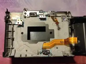
Remove the remaining 3 M1.4 X 2.5 red screws with a JIS 00 screwdriver seen in Picture 1.
-
Remove the shutter and locate a small M1.6 X 4.5 (Tapping) silver screw marked with a red circle in Picture 2 holding the charge unit in place.
-
Transfer the charge unit assembly over to the new shutter unit, or simply replace the charge unit with a new working one, it depends on what replacement part you've bought.
-

To reassemble your device, follow these instructions in reverse order.