Introdução
When the L3 and R3 potentiometers wear out, proper de-soldering equipment will be necessary to safely remove and replace them. De-soldering the parts is challenging, but it can be done.
When purchasing the replacement parts, please choose those for Sixaxis/non-DualShock controllers. The conductive film has a ribbon connector, and the mainboard has a connector port superior to the DualShock 3. Also works on PS4 too just that they are all sandwich job conductive film.
Ferramentas
Peças
-
-
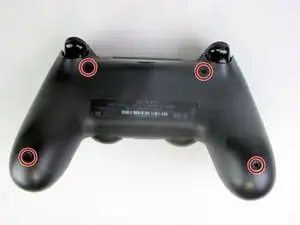
Using the Phillips #00 Screwdriver, remove the four 6.0 mm screws securing the rear cover to the controller.
-
-
-
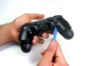
Beginning with the left handle:
-
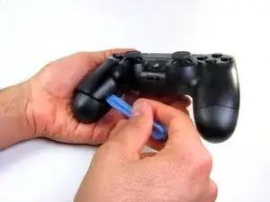
Pinch the left handle of the controller to introduce an opening.
-
Wedge a plastic opening tool into the opening and slide it up towards the joystick.
-
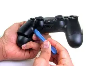
Pull down on tool to pry open the casing.
-
Repeat these steps for the right handle.
-
-
-
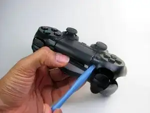
Wedge a plastic opening tool into the case-splittings and pull down to crack open the casing near the following buttons:
-
Share button
-
Options button
-
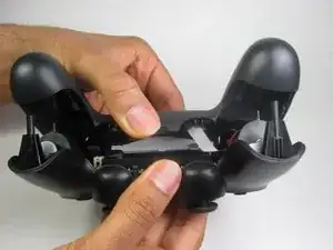
Split the plastic covers of the controller apart, taking note that they will still be attached by circuit board ribbons.
-
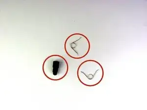
2 Trigger Springs
-
1 Grey Reset Button Extension
-
-
-
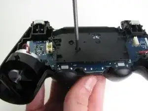
Remove the single 6.0 mm Phillips screw found below the battery retainer with the Phillips #00 Screwdriver.
-
-
-
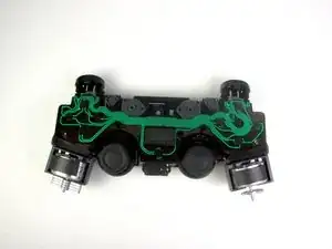
Gently detach the touchpad ribbon connected to the motherboard using the blunt forceps. The touchpad ribbon is connected to the motherboard by a connector that flips to tighten and loosen. During reassembly, to reattach the ribbon, the plastic tray will need to be gently removed from the motherboard and the flip-lock flipped up.
-
-
-
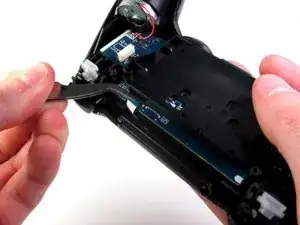
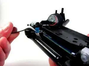
Carefully dislodge the motherboard assembly from the front cover.
-
Vibration motors are loosely attached to the motherboard assembly. Provide support at the two ends to ease the separation.
-
-
-
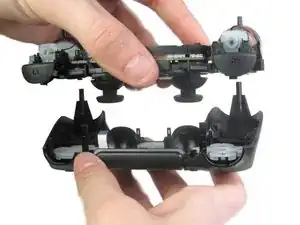
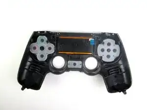
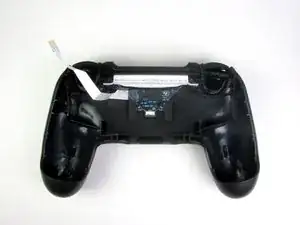
Successful disassembly of the controller will result in the following three parts, respectively:
-
Motherboard Assembly
-
Front Cover
-
Rear Cover
-
-
-
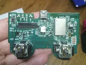
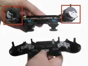
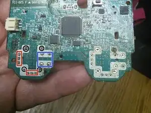
Note the Sixaxis conductive film connector is superior to the DualShock 3.
-
De-solder the four (4) potentiometer through hole mounts.
-
De-solder the six (6) potentiometer through hole joints.
-
De-solder the L3 and R3 button joints, then insert and solder the new potentiometers.
-
Note this mainboard asembly uses lead solder, likely 63/37 eutectic. A 80W soldering iron is strongly recommended for de-soldering and re-soldering operations, as solder tends to not easily flow with less heat transfer.
-
Also works on Dual Shock 4
-
To reassemble your device, follow these instructions in reverse order.
2 comentários
I’ve been looking for “better” (longer lasting) potentiometers but cannot find any. With the rise in DIY controller mods, I don’t understand why better components don’t exist.
get ones off ebay that r usa and metal spring not plastic
Yo usé un Phillips #000, ya que el #00 quedaba grande y podía dañar el tornillo.
Adolfo Gomez Toledo -
A plain #0 works way better for me
Jennica Tapia -
I agree with Jennica, it's a #0 screw
Peeter -
to re-torque these PH00 screw... i found 19Ncm to be about the max. (since 27Ncm was too much)
Dreamcat 4 -