Introdução
Ferramentas
-
-
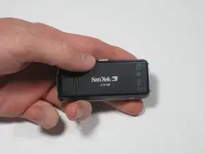
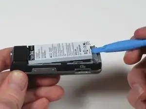
To remove the back cover, slide the back cover toward the top of the device with your thumb.
-
-
-
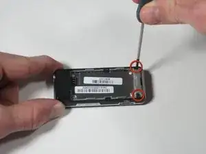
Using a Phillips head screwdriver, remove the two black .265" screws at the base of the device.
-
-
-
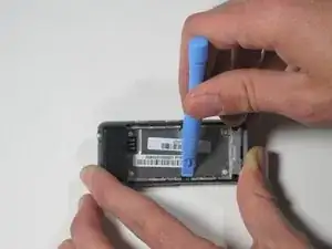
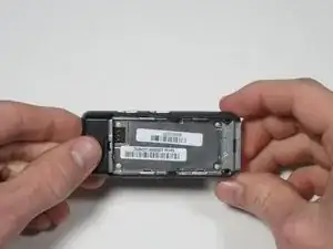
Near the middle of the device, locate the two plastic arms of the case cover.
-
Using the plastic pry tool, pry up the two arms of the case to free them from the sides.
-
-
-
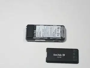
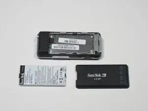
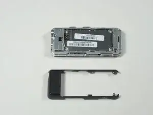
To remove the rear case cover, slide the rear case cover toward the top of the device with your thumb to release it.
-
-
-
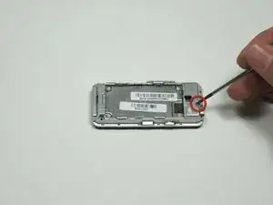
Using a Phillips head screwdriver, remove the single 0.327" silver screw on the back of the device. The screw should be exposed from when you removed the rear case cover.
-
-
-
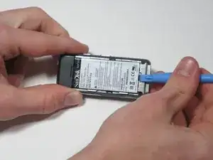
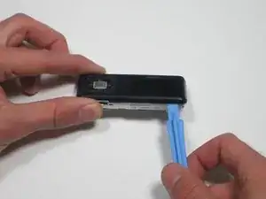
Flip the device over and gently work a plastic pry tool around the base of the front case cover until it loosens.
-
-
-
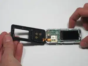
Starting on the side furthest away from the buttons, gently lift the front case cover open with your fingers.
-
-
-
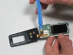
To release the ribbon cable, use a plastic pry tool to gently pry up on where the ribbon cable attaches to the motherboard.
-
-
-
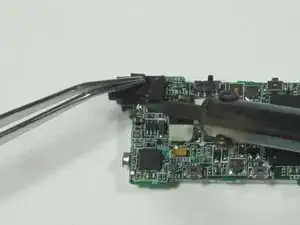
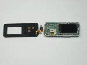
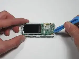
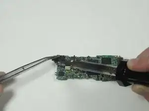
Flip the device over. In one corner, there is a large black component extending past the side of the device. This is the headphone jack.
-
Using a soldering iron, desolder the four points at which the headphone jack connects to the motherboard.
-
-
-
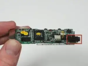
Resolder the new headphone jack to the motherboard, being careful that it is fully attached and in place.
-
Dimensions for headphone jack: 0.230" by 0.541" 1/8" diameter
-
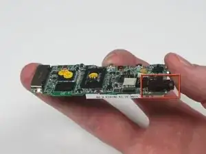
The red box displays the newly installed headphone jack.
-


To reassemble your device, follow these instructions in reverse order.
Um comentário
Sometimes the problem isn't that you need to solder a new jack on but that the jack has become detached from the board or worse the board has started to flake apart (the pad has detached from the board).
So get out your volt meter before you remove the old jack and test to make sure it's the jack that is the problem. My experience is that it is rarely the jack (I've fixed several of these).
There are a couple places on the board where you can solder wires onto if the pads become detached. Just be sure to glue the jack down since the pads aren't anchoring it now (so you don't put added strain on the remaining pads).