Introdução

Follow this guide to replace the logic board (aka main board or motherboard) in your Samsung Galaxy S25 Edge smartphone.

If your device doesn't power on or randomly shuts down, you may need to replace the logic board.

You'll need replacement back cover adhesive to complete this repair.

  1. gRrGFHOvnCPGSi14
    gRrGFHOvnCPGSi14
    SIJAOaG1JcTRhyaM
    • Let your phone's battery drain below 25% before starting this repair. A charged lithium-ion battery may catch fire if accidentally damaged.

    • Completely power off your phone and unplug all cables.

  2. AUKgucWQgIw6abYc
    • Mild adhesive secures the back cover. Heating it will soften the adhesive, making it easier to separate.

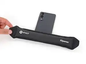
    • Heat an iOpener and lay it on the bottom edge of the back cover for two minutes to soften the adhesive.

    • Alternatively, you can use a hair dryer, heat gun, or hot plate to heat the cover.

  3. MKZYaKnSqRMOttaV
    MKZYaKnSqRMOttaV
    DYNBmtI5KIlNMVyp
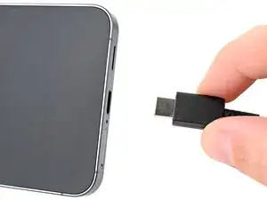
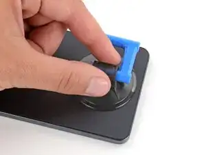
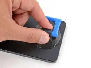
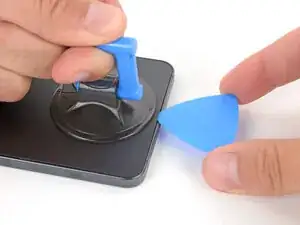
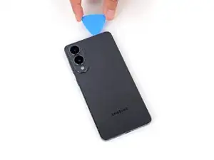
    • Apply a suction handle near the center of the back cover's bottom edge, as close to the edge as possible.

  4. cNHreUvGGgTdMHso
    cNHreUvGGgTdMHso
    FalHG4ZWwBWcXaZ2
    ML4qOdvgkFqeepJZ
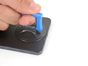
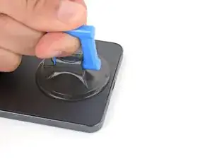
    • Pull up on the suction handle with strong, steady force until a gap forms between the cover and frame.

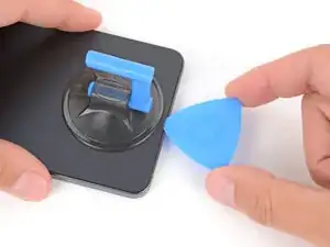
    • Insert the tip of an opening pick into the gap.

  5. pydYLtDqUDE4YDRh
    pydYLtDqUDE4YDRh
    fFkYJ4iEjMtEbSXb
    kuNsiooXAiThndsn
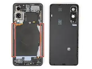
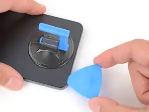
    • The back cover is secured with adhesive around the perimeter of the frame. Use this picture as a reference while you separate the adhesive.

    • When separating the left and right edge adhesive, don't insert your pick more than 3 mm to avoid damaging the wireless charging coil and interconnect cable.

  6. CMsiBVBI5kwUqXOW
    CMsiBVBI5kwUqXOW
    VaLGN3iKlVVhUCTk
    e4nGGwSexGxYRagn
    • If you have trouble separating the adhesive, apply more heat and try again.

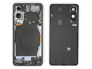
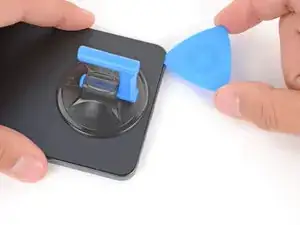
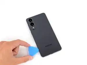
    • Slide your opening pick along the bottom edge to separate the adhesive securing the back cover.

  7. MQxHqTLKpfOwLQHC
    MQxHqTLKpfOwLQHC
    HMS5xDmgPWIZRwFn
    D2ndMNVjVM6vdnfd
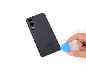
    • Continue sliding your pick around the entire perimeter of the back cover to separate all the remaining adhesive.

    • Remember not to insert your pick too far under the long left and right edges.

  8. cCmWGpNnHEs2Rds1
    cCmWGpNnHEs2Rds1
    EkOvtCDKRdXTSqrj
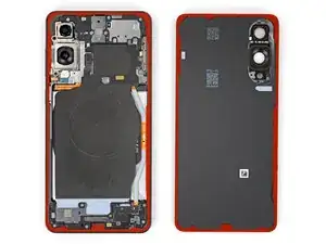
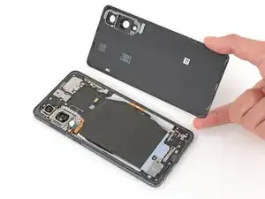
    • Remove the back cover.

    • If you're having trouble, check the perimeter for any remaining adhesive and use your opening pick to separate it.

    • During reassembly:

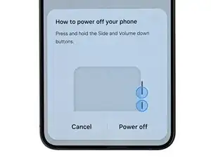
    • This is a good point to power on your phone and test all functions before sealing it up. Be sure to power your phone back down completely before you continue working.

    • Check your rear cameras for any smudges and gently wipe them with a clean lint–free cloth if necessary.

    • Your replacement back cover adhesive will be applied to either the frame or the back cover. Use cutouts and contours to see where it lines up best. If it matches the back cover, follow this guide. If it matches the frame, use this guide.

  9. 1fRv1fV12gvcDQbb
    1fRv1fV12gvcDQbb
    WGwxhlnuWIRjQlWO
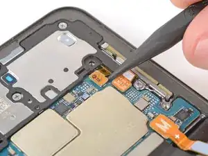
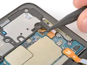
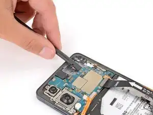
    • Use the point of a spudger to pry up and disconnect the wireless charging assembly press connector from its top edge.

    • Getting the spudger under the connector can be tricky. If you're having trouble, try using the tip of an opening pick instead.

  10. ZZ1TYFCZd2h4SEZc
    ZZ1TYFCZd2h4SEZc
    JuGasFR5i21jcCYp
    BCZUXmlCiDnQFVlJ
    • Throughout this repair, keep track of each screw and make sure it goes back exactly where it came from.

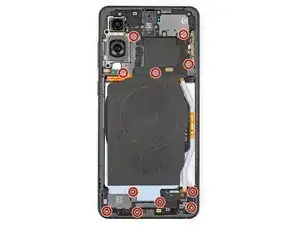
    • Use a Phillips screwdriver to remove the eleven 2.8 mm‑long screws securing the wireless charging and loudspeaker assembly.

  11. rIxbjnIn2FM1BFZs
    rIxbjnIn2FM1BFZs
    3MbR2OPK56ovnDDG
    YZwsHeR1ZBXyLiDo
    • The wireless charging coil is connected to the loudspeaker with delicate tape. It's easiest to remove the coil and loudspeaker together as one assembly to avoid damage.

    • Use angled tweezers to pry up and unclip the loudspeaker by the notch on its left edge.

    • During reassembly, press down firmly around the perimeter of the loudspeaker to engage its clips.

  12. D1kANNWXUXwMu6XG
    D1kANNWXUXwMu6XG
    koJQCO1JHnoDu2me
    • Use two hands to lift and remove the wireless charging and loudspeaker assembly.

  13. LWh51vKjKZUN2viw
    LWh51vKjKZUN2viw
    MTSMykZjgmxSLPtU
    • Every press connector has a corresponding gold arrow on the board that shows the proper location to pry—nifty! Prying at the wrong location risks damaging the fragile surface‑mounted components on the board.

    • Use the point of a spudger to pry up and disconnect the battery press connector.

  14. yGqBPJyVFua4GbMU
    yGqBPJyVFua4GbMU
    DZ2hNsWmkJtMHg2p
    • Use the point of a spudger to pry up and disconnect the earpiece speaker press connector.

  15. 3SIphZnkQltYZsP5
    3SIphZnkQltYZsP5
    kAnrqCVZBCt1gGWB
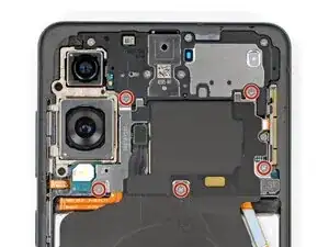
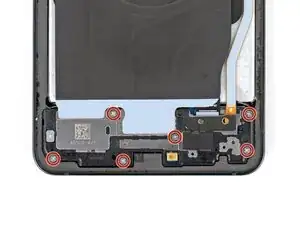
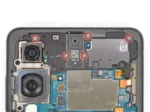
    • Use a Phillips screwdriver to remove the five 2.8 mm‑long screws securing the earpiece speaker.

  16. QHcoDZpqLNHOeZZF
    QHcoDZpqLNHOeZZF
    WrivMNJhnKRyQwog
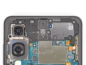
    • Use the flat end of a spudger to pry up and unclip the earpiece speaker from the center of its bottom edge.

    • During reassembly, press down firmly around the perimeter of the earpiece speaker to engage its clips.

  17. xAFBBEHMNt3tumCp
    xAFBBEHMNt3tumCp
    Vc2KGHISmCqc3N4s
    • Lift and remove the earpiece speaker.

  18. kvH5QhybttIDCofL
    kvH5QhybttIDCofL
    ySGEiHDxlmmw3cIM
    LAuCJDXEGvH3M4Fg
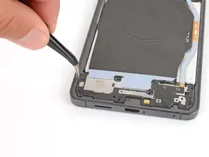
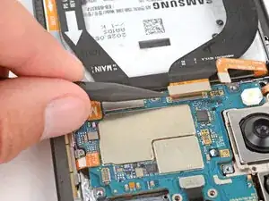
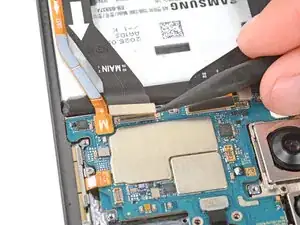
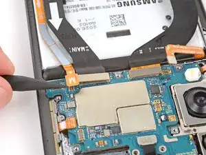
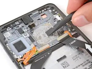
    • Use the point of a spudger to pry up and disconnect the screen, USB‑C, and interconnect cable press connectors (three total) from the logic board.

  19. jEPkAi3UekUHlLO4
    jEPkAi3UekUHlLO4
    m2bd5qLXEWooB4Uj
    LoZTDYoyWaJUApc4
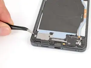
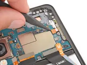
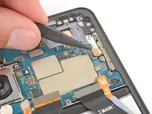
    • Use the point of a spudger to pry up and disconnect the 5G mmWave antenna and front camera press connectors.

  20. 1LjVJavuAR4Ig4r1
    1LjVJavuAR4Ig4r1
    6BWAZeajHDcNfQuQ
    • Use a Phillips screwdriver to remove the two 2.8 mm‑long screws securing the rear cameras.

  21. y2RFyBUurvRGSrs4
    y2RFyBUurvRGSrs4
    vKMgbEfHaTZYsEG1
    RgQyshbUYKbMFKAJ
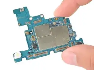
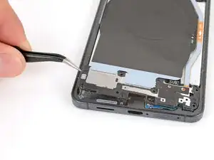
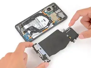
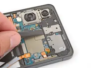
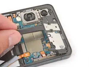
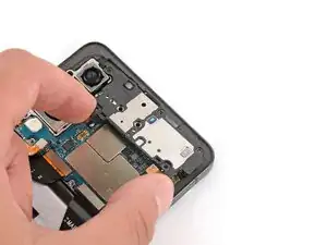
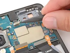
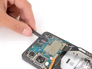
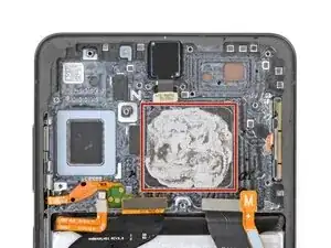
    • Use the flat end of a spudger to lift the top edge of the logic board until you can grip the edges with your fingers.

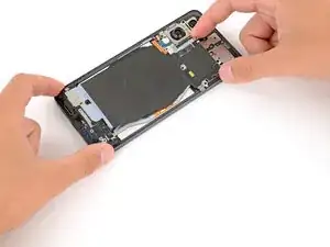
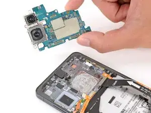
    • Grip the edges of the board and carefully lift it out, making sure not to snag any cables.

    • Don't grip the board by the rear cameras, or you may smear or damage them.

    • During reassembly, make sure no cables get stuck under the logic board when lowering it into place. You can use a spudger to hold the cables out of the way.

  22. NIiFVQ2vBJv3OOZA
    NIiFVQ2vBJv3OOZA
    YrZJWfEdDRKN41iT
    F6g1tpGMWVJJxFSB
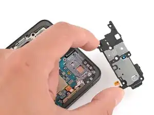
    • Hold the logic board slightly above your work surface while working on the cameras—don't press the board against your work surface, or you may damage fragile components.

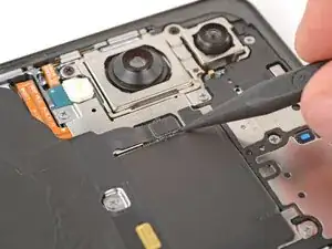
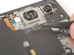
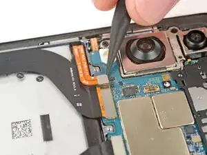
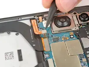
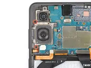
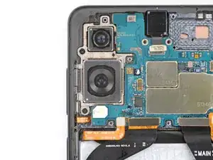
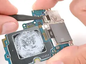
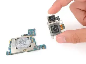
    • Use the point of a spudger to pry up and disconnect both rear camera press connectors.

  23. hRbyOTHJaPBHL4NS
    • Remove the rear cameras from the logic board.

    • Depending on your repair, either one or both components are available to replace.

    • During reassembly, compare your replacement part to the original. You may need to remove plastic liners, adhesive backings, or protective covers.

  24. CJFXLtQNlvFOtLZB
    CJFXLtQNlvFOtLZB
    pU4NHYDfJb6FPRWr
    • The thermal paste sits on top of the vapor chamber, which dents easily. Work gently with minimal pressure, and don’t worry if you can't remove every last bit of the paste.

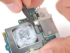
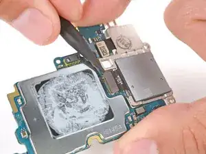
    • Use the flat end of a spudger to gently remove as much of the old thermal paste as you can.

  25. 6V4m3iaLnLnZmKiY
    6V4m3iaLnLnZmKiY
    N4T5jYPv2dOvAPH6
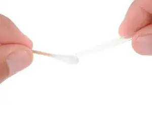
    • Apply one or two drops of high‑concentration (>90%) isopropyl alcohol to a cotton swab.

    • Don't apply isopropyl alcohol directly to the phone, or it may leak onto the screen.

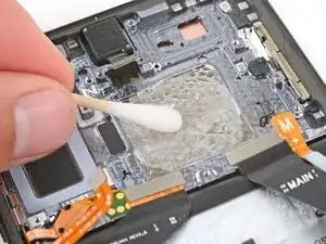
    • Use the cotton swab to clean up and remove the remaining thermal paste from the vapor chamber, applying more alcohol to the swab as necessary.

  26. F6J3fS4NWt5njYgl
    • The film on the bottom of the logic board is fragile—avoid touching it.

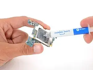
    • Carefully apply a small bead of thermal paste (about the size of a grain of rice) to the center of the black film on the bottom of the logic board.

Conclusão

Compare your new replacement part to the original part—you may need to transfer remaining components or remove adhesive backings from the new part before you install it.

To reassemble your device, follow these instructions in reverse order.

Take your e-waste to an R2 or e-Stewards certified recycler.

Repair didn’t go as planned? Try some basic troubleshooting, or ask our Answers Community for troubleshooting help.

Spencer Day

Membro desde: 14/09/22

165254 Reputação

0 comentários