Introdução
Follow this guide to replace the USB-C port and charging board on your Samsung Galaxy S23 Ultra.
Note: Retaining water resistance after the repair will depend on how well you reapply the adhesive, but your device will lose its IP (Ingress Protection) rating.
-
-
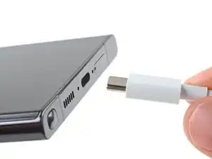
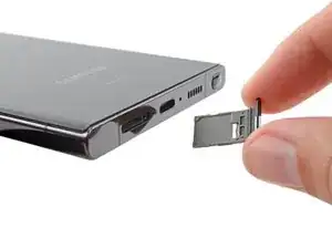
Insert a SIM eject tool, bit, or straightened paper clip into the SIM card tray hole on the bottom edge of the phone.
-
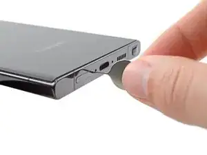
Press the SIM eject tool into the SIM card tray hole to eject the SIM card tray.
-
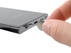
Remove the SIM card tray.
-
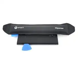
-
-
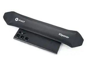
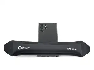
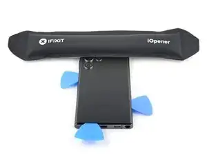
While you wait for the adhesive to soften, note the following:
-
There's adhesive securing the back cover around the perimeter of the frame.
-
-
-
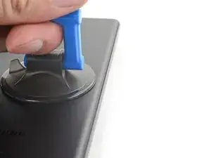
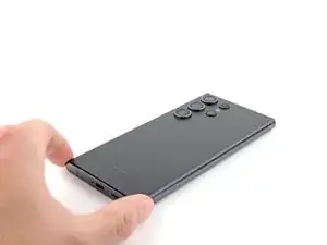
Apply a suction handle to the back cover, as close to the center of the right edge as possible.
-
Pull up on the suction handle with strong, steady force to create a gap between the cover and the frame.
-
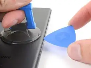
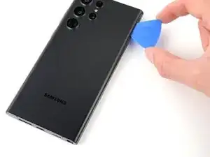
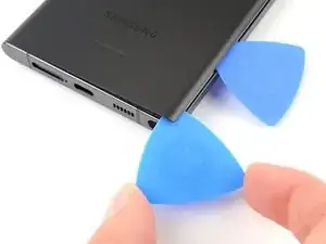
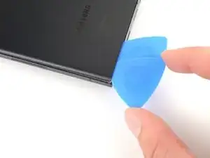
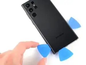
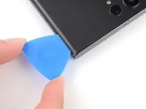
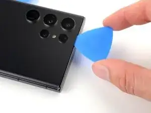
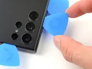
Insert an opening pick into the gap.
-
-
-
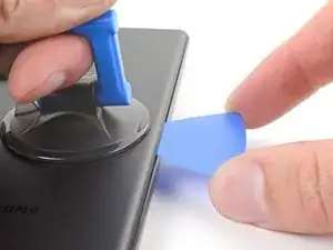
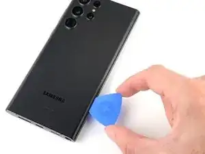
Slide the pick back and forth along the right edge to separate the adhesive.
-
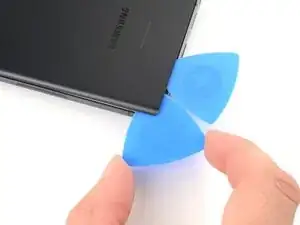
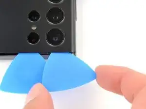
Leave the pick inserted near the bottom right corner to prevent the adhesive from resealing.
-
-
-
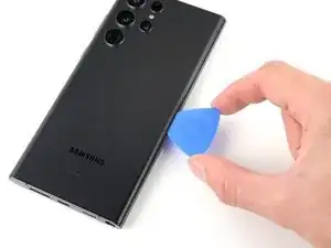
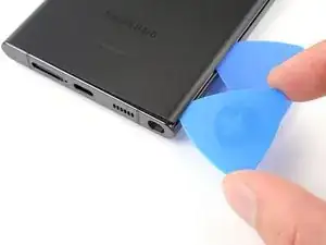
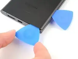
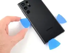
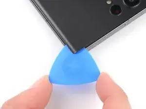
Insert a second opening pick at the bottom right corner.
-
Angle the pick upward to match the curved edge and rotate it around the bottom right corner.
-
-
-
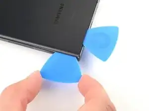
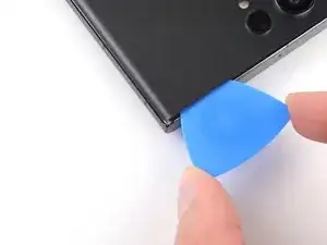
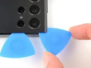
Slide your opening pick to the bottom left corner to separate the adhesive.
-
Leave the pick in the bottom left corner to prevent the adhesive from resealing.
-
-
-
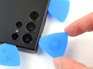
Insert a third opening pick at the bottom left corner.
-
Angle the pick upward to match the curved edge and rotate it around the bottom left corner.
-
-
-
Slide your opening pick along the left edge to separate the adhesive, stopping when you reach the power button.
-
Leave the pick in the left edge to prevent the adhesive from resealing.
-
-
-
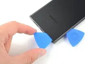
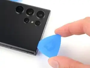
Insert an opening pick in the gap at the top right edge.
-
Angle the pick upward to match the curved edge and rotate it around the top right corner.
-
-
-
Slide the pick to the top left corner to separate the adhesive.
-
Leave the pick in to prevent the adhesive from resealing.
-
-
-
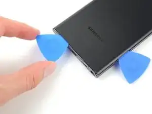
Insert an opening pick in the gap at the top left edge.
-
Angle the pick upward to match the curved edge and rotate it around the top left corner.
-
-
-
Slide the pick toward the bottom camera to separate through the remaining adhesive, stopping before you reach the power button.
-
-
-
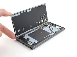
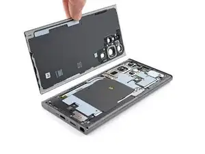
Grab and remove the back cover.
-
Remove any adhesive chunks with a pair of tweezers or your fingers. Apply heat if you're having trouble separating the adhesive.
-
If you're using custom-cut adhesives, follow this guide.
-
If you're using double-sided tape, follow this guide.
-
-
-
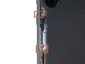
Use the pointed end of a spudger to pry up and disconnect the NFC antenna press connector from the motherboard.
-
Repeat for the wireless charging coil press connector.
-
-
-
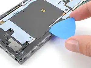
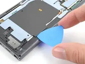
Insert an opening pick between the right edge of the wireless charging coil and the battery.
-
Slide the pick along the right edge to separate the adhesive.
-
-
-
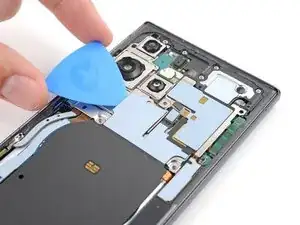
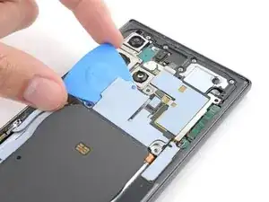
Insert an opening pick between the top edge of the wireless charging coil and the frame.
-
Slide the pick toward the right edge to separate the remaining adhesive.
-
-
-
Use a Phillips screwdriver to remove the five 3.5 mm-long screws securing the NFC antenna and charging coil.
-
-
-
Insert the pointed end of your spudger between the upper right corner of the loudspeaker and the frame.
-
Pry up to unclip the loudspeaker from the frame.
-
-
-
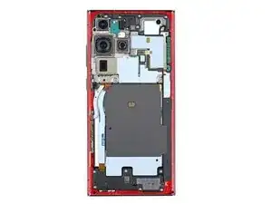
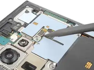
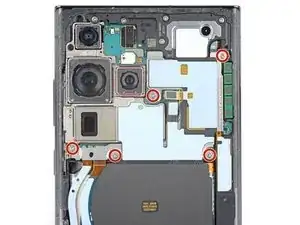
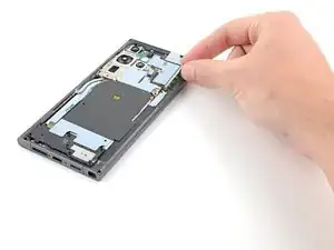
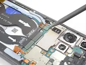
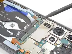
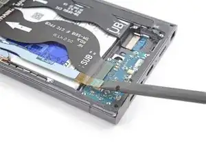
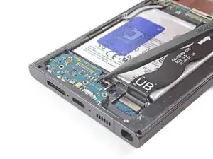
Use your spudger to pry up and disconnect the secondary interconnect cable press connector from the motherboard.
-
Repeat for the primary interconnect cable.
-
-
-
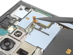
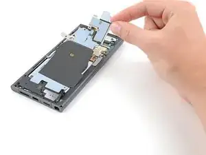
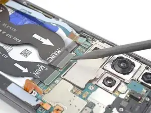
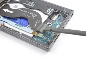
Use your spudger to pry up and disconnect the secondary interconnect cable press connector from the charging board.
-
Repeat for the primary interconnect cable.
-
-
-
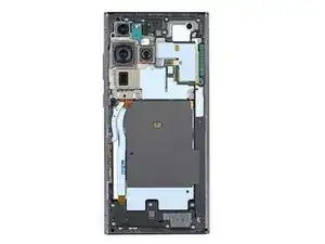
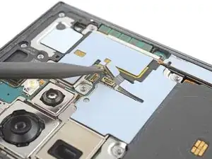
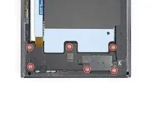
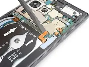
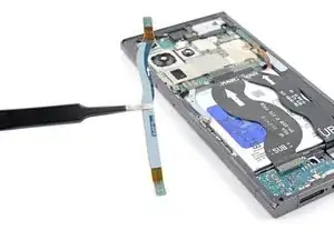
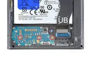
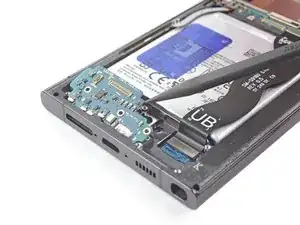
Use a Phillips screwdriver to remove the three 3.5 mm-long screws securing the charging board.
-
-
-
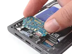
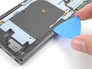
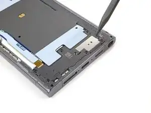
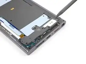
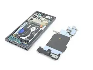
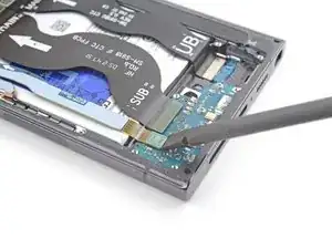
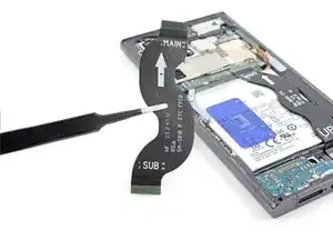
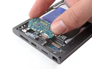
Insert the point of your spudger under the top right of the charging board.
-
Pry the charging board up from its recess until you can grab it with your fingers.
-
Pull the charging board toward the top of the device to remove it from its recess.
-

To reassemble your device, follow the instructions in reverse order and perform the opposite actions, e.g., "reattach" instead of "removing." Skip steps that use heating and prying, and pay close attention to the 📌 bullets as you work through the steps.
After you've completed the repair, download the Samsung Members App from the Galaxy Store or the Play Store, and Samsung Self-Repair document (beginning page 10) to make sure your device is fully functional.
Take your e-waste to an R2 or e-Stewards certified recycler.
Repair didn’t go as planned? Check out our Answers community for troubleshooting help.

4 comentários
Muchas gracias por el conocimiento entregado, de muy buena calidad!!
I like this repair.i will attempt it when I go home.
Very helpful guide. The hardest part is just getting it open, but once that was over it was pretty much smooth sailing. I got the iFixit kit and had trouble with the iOpener with getting the back cover off. I'm not sure if it wasn't hot enough, so I resorted to using a hair dryer instead. Otherwise, fantastic guide.
My local Verizon store said it would cost $70 for them to clean the charging port, and if that didn't fix the issue it could be several hundred dollars to repair it. Between the iFixit opening kit, the part on Amazon, and some adhesive, I spend less than $50 plus my time.