Introdução
-
-
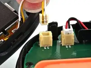
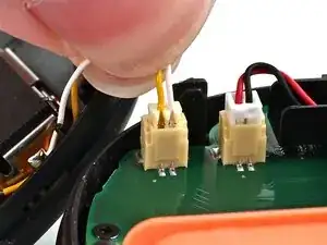
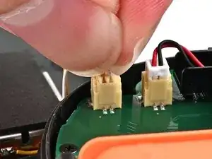
Align the rumble motor connector to its socket on the bottom edge of the board, and push down until it's fully seated to connect it.
-
-
-
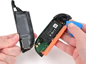
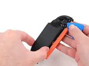
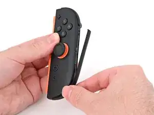
Use an opening pick to press and hold the release button.
-
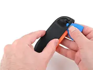
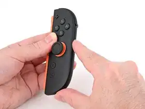
Place the back cover over the controller body so the release button cutout is slightly below the release button.
-
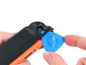
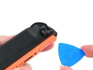
Press and slide the back cover up until the cut-out for the release button is aligned with the button itself.
-
-
-
Install the two screws on the right edge of the controller:
-
One 3.1 mm‑long tri-point Y00 black screw
-
One 3.0 mm‑long JIS 00 silver screw
-
-
-
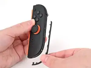
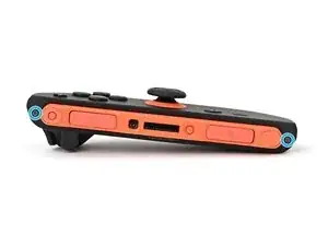
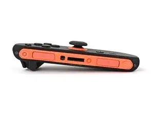
Align the clips on the plastic strip with their cut-outs on the right edge of the controller body.
-
Insert the clips on the bottom edge first, then insert the rest so the plastic strip sits flush.
-
-
-
Use a tri-point Y00 driver to install the two 3.1 mm‑long black screws on the left edge of the controller.
-

To reassemble your device, follow these instructions in reverse order.