Introdução
Based on lenovo_legion_9_16irx9_hmm.pdf "Hardware Maintenance Manual" from https://pcsupport.lenovo.com/si/en/produ... also shown below as a "Featured Document". See page 44.
Ferramentas
-
-
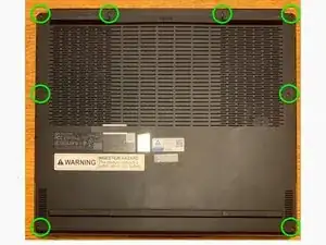
Flip the computer over to access the screws on the bottom.
-
Remove 8 black, 7mm PH0 screws (M2 x L7).
-
Note: Virtually all the other screws for this computer are PH1 screws which may get stripped when using a smaller screwdriver, but these screws require a Philips PH0 driver.
-
-
-
Pry up the clips/latches and then remove the lower case. Start at the front (four clips), then sides (three clips each side) and back (four clips) - there is also one clip in the middle of the case.
-
-
-
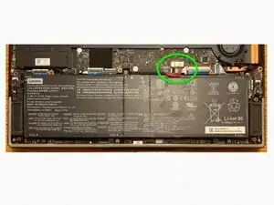
Almost anything that is done with a computer is safer if the battery is disconnected, so it is good to do that now.
-
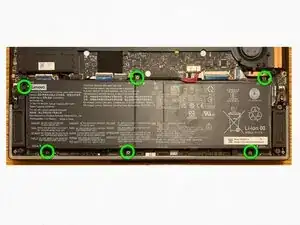
Disconnect the battery pack cable from the system board using fingernails or a pry bar. Use your fingernails to pull the connector to unplug it. Do not pull the cable. It can be very tight. I used a 3.5 mm flathead screwdriver to carefully push the side plastic edges down towards the battery. Do not knock any of the components on the board.
-
-
-
Remove 6 black 4mm PH1 screws (M2 x L4). The lower right screw is close to a magnet that may pull it from where you want it to go - tweezers may be necessary. The Hardware Maintenance Manual does not show the bottom middle screw.
-
Note: Virtually all the screws for this computer are PH1 screws which may get stripped if you use a smaller screwdriver.
-
-
-
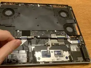
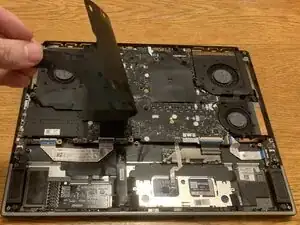
Remove the system board mylar.
-
Note: Retain the system board mylar and reuse it when reassembling the computer. Replace the system board mylar only if it is damaged.
-
-
-
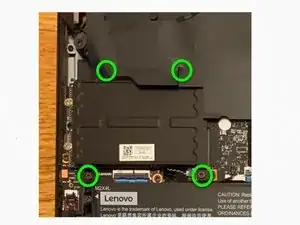
Remove 4 black PH1 screws (M2 x L4) and then remove the SSD shielding.
-
Note: Virtually all the screws for this computer are PH1 screws which may get stripped if you use a smaller screwdriver.
-
-
-
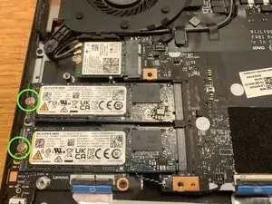
Remove 2 silver 2mm PH1 screws (M2 x L2), one for each SSD.
-
Note: Virtually all the screws for this computer are PH1 screws which may get stripped if you use a smaller screwdriver.
-
-
-
Remove each SSD by pulling it away from the slot.
-
Note: it may be important to replace the SSDs into the same slot, so label them in some manner - perhaps "T" for the top one and "B" for the bottom one.
-
-
-
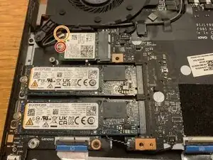
Detach the main and auxiliary antenna cable connectors. Note which colour cable is connected to each post - the photographed board has a grey cable connected to the top post (marked as "#1 Aux" with a white triangle on the Wi-Fi card) and a black cable connected to the bottom post (marked as "#2 Main" with a black triangle on the Wi-Fi card).
-
Remove 1 silver 2mm PH1 screw (M2 x L2).
-
Note: Virtually all the screws for this computer are PH1 screws which may get stripped if you use a smaller screwdriver.
-
Remove the Wi-Fi card by pulling it away from the slot.
-
-
-
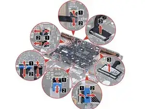
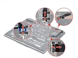
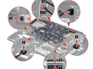
(1) Peel off the thermal DIMM plate tape from the system board.
-
(2-3) Lift flap and disconnect the I/O board cable from the system board.
-
(2-3) Lift flap and disconnect the audio FPC cable from the system board.
-
(2-3) Lift flap and disconnect the hinge cap lightingbar cable from the system board.
-
Note: my machine did not have the DIMM plate tape or the cable in the upper right.
-
-
-
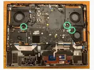
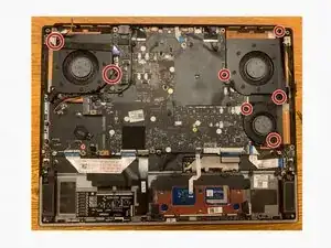
Remove 7 black 6mm PH1 screws (M2 x L6) holding the fans.
-
Note: Virtually all the screws for this computer are PH1 screws which may get stripped if you use a smaller screwdriver.
-
Remove tape from fans - possibly using gentle heat
-
Remove the fans - be careful of Wi-Fi antenna cables around top left fan and speaker cable around small bottom right fan.
-
-
-
Remove 3 black 4mm PH1 screws (M2 x L4) screws
-
Remove 2 black 6mm PH1 screws (M2 x L4) screws
-
Note: Virtually all the screws for this computer are PH1 screws which may get stripped if you use a smaller screwdriver.
-
Remove the flaps of tape holding the antenna wires to the board.
-
Remove the system board module carefully.
-
To reassemble your device, follow these instructions in reverse order.