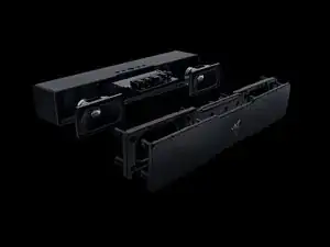
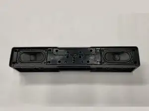
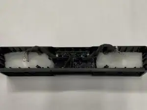
Introdução

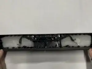
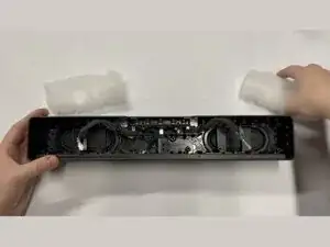
Repairability rating 8/10. Easy for beginners, great speaker housing for modders. Overall Razer did a quite good job making this decently easy to disassemble.

  1. Xf1stBRViEQhSLAL
    Xf1stBRViEQhSLAL
    OifatRfLyGQOCbJY
    vYZZNTjLJQRUYJNg
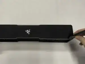
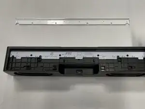
    • Using a flat metal "Jimmy" tool, gently work out the front metal screen and mesh.

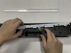
    • Insert the tool vertically ~3-5mm (~1/8-1/4in), then pry gently away from the mesh screen. The screen should slowly start to come out directly vertical.

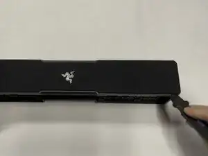
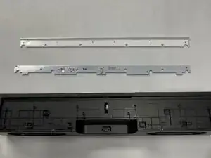
    • Repeat this every few cms/inches, working in a loop around the outside edge one or two times until you get the metal/mesh screen off.

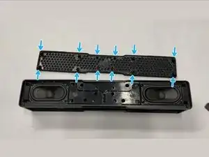
    • On the bottom of the metal/mesh screen there are 12 protruding plastic tabs that are inserted ~2cm into the body of the speaker.

    • It should come directly vertically up with very little to no pressure if you get the tool angle just right. Be patient, and work slowly.

  2. QyHIsaF1yUyFCpON
    QyHIsaF1yUyFCpON
    wsGsKWdPFV6RMJxY
    h1AZaKUcNvXO1x1c
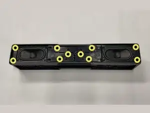
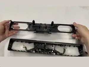
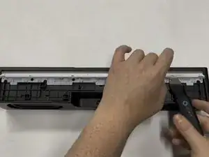
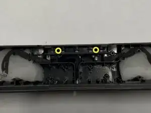
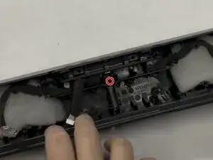
    • Use a Philips #2 screwdriver to remove the ten 14 mm-long screws mounting the inner frame to the body.

    • Note: There are helpful plus sign/star symbols next to each hole that has a screw in it! See the third image, they look similar to this: ✦

  3. 5nW65iMcfyD2hLuH
    5nW65iMcfyD2hLuH
    OqDYeP1WTaIem5nt
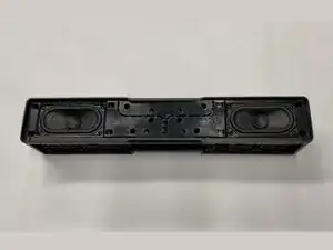
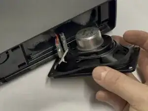
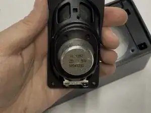
    • Use a Philips #2 screwdriver to remove the eight 14 mm-long screws holding in the two speakers.

    • These screws are the same size as the screws from the previous step

  4. xVK2HZ4JMeeXTya1
    xVK2HZ4JMeeXTya1
    v5fraIVVZqHNlQvh
    • Lift the speaker from the body to get at the wires.

    • Make sure to keep the thin gasket with the speaker for vibration isolation.

  5. jTnYgLbJRykIQvaC
    jTnYgLbJRykIQvaC
    ZwPlPPokjechiJWS
    Hb4WGfhypX4TsrI3
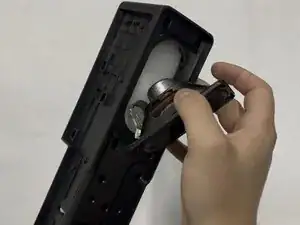
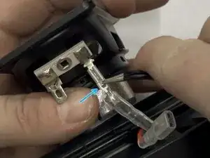
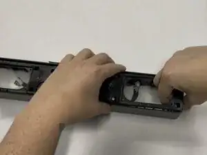
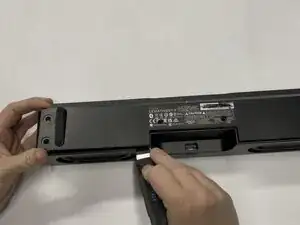
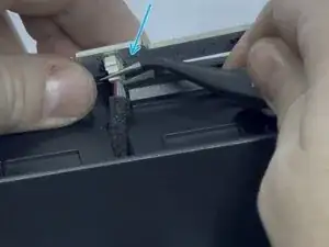
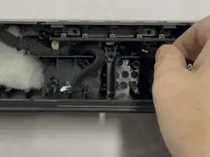
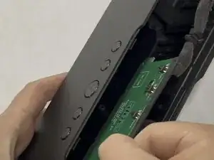
    • Slip the plastic cover downward off the connector

    • Use metal tweezers or a tiny driver bit to press down the tab in the center of the connector.

    • Gently pull downward on the connector to disconnect it from the body.

  6. mEdfHv1ybVgNVHpD
    • Remove each of the two speakers and set them aside.

    • Speaker Details: 2″×4″ 2Ω 5W speaker (MS41230)

  7. H6lwBi1YNO1OgwBB
    H6lwBi1YNO1OgwBB
    cBfTVKUmtXSXnGjE
    JjPFKe4l6aYudrDX
    • Pull on each side of the inner plastic frame vertically to slide it out of the body.

    • If you have to apply force, first re-verify that you have removed all 18 screws from Steps 2 and 3.

    • You can use the speaker holes as handles to grip the frame.

  8. LuGWOiJqOdZhxS2p
    LuGWOiJqOdZhxS2p
    1XCV5bOFPRnCYwbO
    GPF61fPeRrB1sVPB
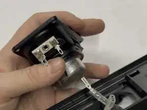
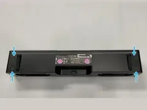
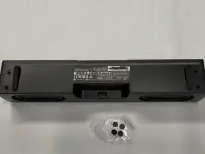
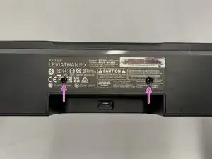
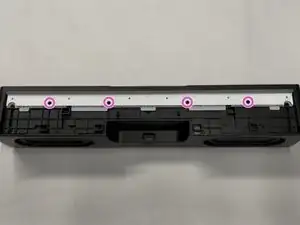
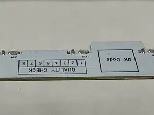
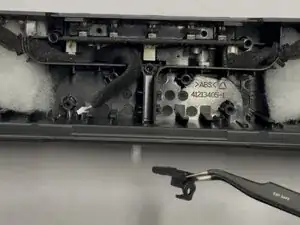
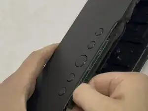
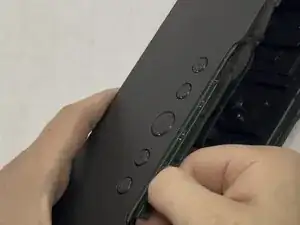
    • Remove the 4 sticky screw covers from the bottom of the speaker

    • Tip: Place these on clean plastic or wax paper and you will be able to easily reuse them, but we suggest tossing them and showing off the screws after reassembly!

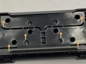
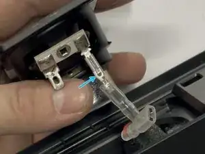
    • Use a Knife to cut through the sticker to reveal two more hidden screws. See image #3

  9. RqatvFoIlOmqquLR
    RqatvFoIlOmqquLR
    ZEqMEQgLsHXRMqcE
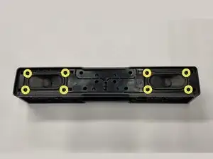
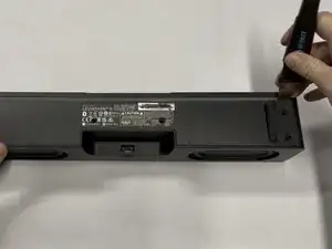
    • Use a Philips #2 screwdriver to remove the six 10 mm-long screws holding the bottom cover in place

  10. HxWbOuu4ZHoAWeRB
    HxWbOuu4ZHoAWeRB
    SBUZQeUmcUtwdHs5
    CMSLZAEtnsnfwwaP
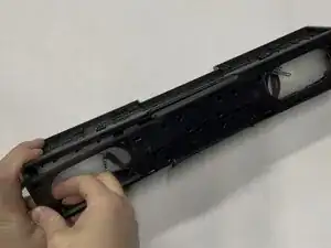
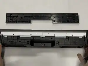
    • Use the Jimmy tool to remove the bottom cover, again working slowly around outside of the part. It should come off with little force needed.

    • If you have to use force to remove bottom cover, re-verify you have removed all six of the screws!

  11. YKCWNFWiOCFZMQ41
    YKCWNFWiOCFZMQ41
    fIF5JwVDhihho2Qv
    sOBvoPpELXCAthNa
    • Use a Philips #1 screwdriver to remove the four 8 mm-long screws holding in the RGB diffuser and board

    • Note: For this step you need a smaller screwdriver than all of the other steps.

    • Slip Jimmy tool between the light bar diffuser and PCB then lift gently upward, then remove the light bar diffuser and set aside

  12. 6Afd5XHLCVW1E6XW
    6Afd5XHLCVW1E6XW
    iNpJgHYXOPQBvCXe
    rhdHfAGKT2I32Coy
    • Gently pry the RGB board free using the jimmy tool and lift it upwards and away from the bottom.

    • Warning: The RGB Board has a connector on the bottom side, be gentle as you pull upwards!

    • Disconnect: Using a tool or your fingers, unplug the connector on the RGB board, then set it aside

  13. T6kXHMVOykVJdmvi
    T6kXHMVOykVJdmvi
    AHU5QgBpQePr5hJG
    RHBJRAhS5PmMR5Hr
    • Close up detail views of the RGB Light Bar PCB. Very simple design.

  14. RZheupNEKVZp34AL
    RZheupNEKVZp34AL
    b1IdmNKMQoMsGMGu
    • Use a Philips #2 screwdriver to remove the two 14 mm-long screws holding in the main board.

  15. 6eKhaJuTpapEoP2K
    6eKhaJuTpapEoP2K
    MhwZJMHf4VQSrYSP
    LymtFCnjLRbF3T1U
    • Pull on the cable for the RGB board and move it to the side to expose the bracket

    • Use a Philips #2 screwdriver to remove the single 10 mm-long screw holding the USB-C bracket in place

    • Note: This screw is the same size as the six screws for the bottom cover.

    • Lift and remove plastic bracket covering USB-C Port

  16. vLZPBuH6P24IFFUM
    vLZPBuH6P24IFFUM
    GLu5iDW55BabtqdU
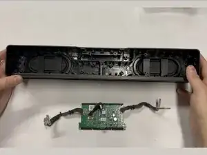
    • Slip the speaker cables from their wedged positions and remove the white polyester batting that was behind the two speakers

    • Reminder: Leave the foam insulation around the speaker wires, it is there to dampen vibrations and keep the speaker sounding clean.

  17. YDrFdVVVuCDeNMIA
    YDrFdVVVuCDeNMIA
    nCV1wlna1IL5FlZ1
    y5iJRDSGf4ne2UVm
    • Be careful to not damage/bend the USB-C port!

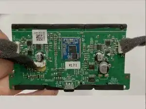
    • Firmly grasp the main board with your fingers and gently wiggle back and forth while pulling the board firmly outward.

    • Additionally pull at a slight angle downward and away from the buttons to help dislodge the USB-C port.

    • The USB-C port is still embedded in the outer frame of the speaker. The intent of this wiggling is to free the USB-C port from the frame of the speaker. This is the only thing still holding the main board in place.

    • Continue this wiggling motion until you have gently worked the board out of it's place.

    • Note: The main board is pretty wedged in there, so it does take some force to remove. Just be patient, go slow, and it will all be okay.

  18. WMg3k4rdIGBgSCyr
    • Remove the main board from the unit and set it aside! 🎉

  19. OOQRAkgBUvYJyeTx
    OOQRAkgBUvYJyeTx
    SEx6JyXsNU1wabML
    lNaUhKGHgkt1yeMd
    • Close up detail views of the main board.

    • Embedded Board: ATS2833 Bluetooth-audio module

  20. osZBOfZPuGMenM2p
    • Follow this guide in reverse to reassemble your device, paying attention to the screw sizing and placement.

    • The two rubber "Passive Radiators" on the back of the speaker body are fused to the housing and do not seem removable. If you find a safe way to remove and reattach these, please leave a comment or update this guide.

Conclusão

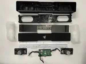
🎉 Complete! 🎉 Hope this guide helped you! 🤩

Sky Young

Membro desde: 28/06/18

910 Reputação

0 comentários