Introdução
Ferramentas
-
-
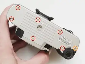
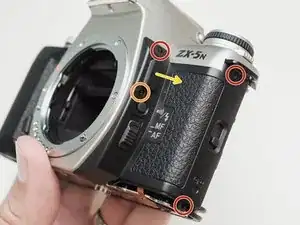
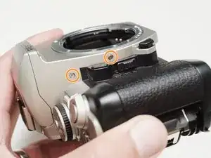
Remove three 5.3 mm #00 screws (the bottom-most screw is not always present).
-
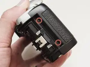
Remove one 7.3 mm #00 screw.
-
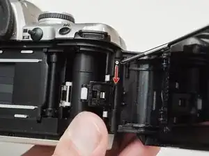
Remove the remote trigger cover.
-
-
-
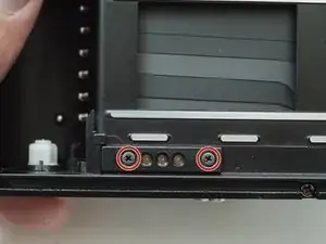
Remove two 3.4 mm #00 screws. Remove the plate holding the contacts in place.
-
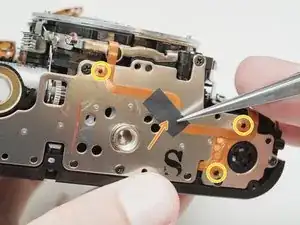
Peel tape from the plate. Leave the tape attached to the flex circuit.
-
Remove the flex circuits from their retaining studs.
-
-
-
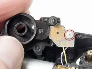
Remove one 3.3 mm #0 countersunk screw.
-
Remove one 3.9 mm #0 shoulder screw.
-
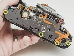
Remove four 3.3 mm #00 screws.
-
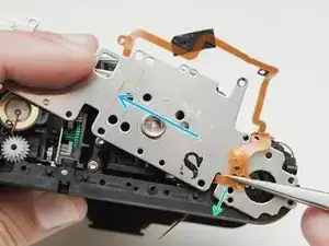
Pull a little slack through the housing on this flex cable.
-
Pop the plate off its posts, rotate slightly clockwise and pull gently through the loosened flex cable.
-
-
-
Gently pull the speaker from its retention posts.
-
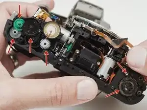
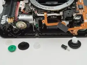
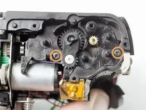
Remove two 5.1 mm #00 screws.
-
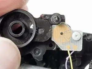
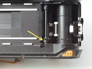
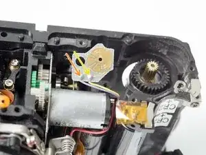
Installation Notes: The transport gear carrier mates with the sprocket shaft here using a squared off spindle. Make sure they mate properly when reassembled.
-
To reassemble your device, follow these instructions in reverse order.
4 comentários
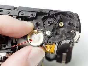
I replaced that pcb component,but these gaps are not stable. Sometimes wide sometimes overlap.Do you have any solutions about this problem?
Hmm, that's a bummer. First I would make sure that your replacement PCB looks like this. The green color isn't important but the contacts should be gold not silver.
https://www.pentaxforums.com/forums/8-fi...
You might have to double check the installation, make sure no debris or hairs got in the mechanism. Make sure the sweepers didn't get bent or misshapen.
I will say that the converted camera may not give you perfect results. I usually get about one frame overlap per roll, but the vast majority of frames are good. It's not uncommon for even stock MZ cameras to have frame advance issues, so it might be related to the mod or it might not.
I solved it! Although the gap is unstable but it has some rhythm. Also! There is no overlap anymore!
My pcb component is silver,not gold.I think it might caused by the film mask which is cut from instaxfilm cover.Maybe too thick that can’t properly advancing film.I will try to stick it direct in the full frame area.hhhhhhh hopefully might help,otherwise I have to get some gold pcb….