Introdução
Ferramentas
-
-
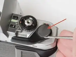
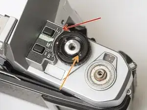
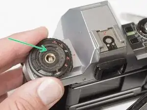
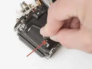
Remove the rubber decorative cap. It is attached with contact cement underneath. Isopropyl Alcohol may be used to soften the adhesive.
-
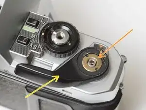
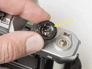
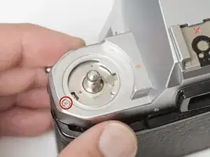
Unscrew the lock nut using a spanner wrench. The lock nut is reverse threaded.
-
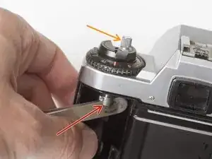
Lift off the advance lever.
-
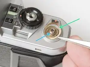
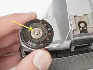
Remove the spring washer.
-
Remove one shim washer.
-
-
-
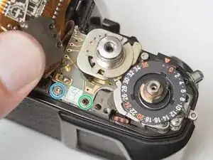
Set the mode dial to the 'L' position.
-
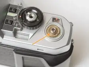
Use a spanner wrench to unscrew the dial lock nut.
-
Lift off the mode dial.
-
-
-
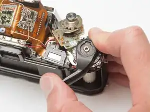
Place a rigid object in the fork.
-
Unscrew the rewind lever.
-
Use a spanner wrench to remove the lock nut.
-
Lift off the exposure compensation dial.
-
-
-
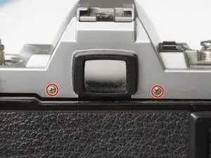
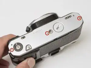
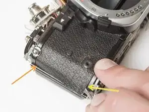
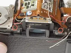
Remove two screws on either side of the eye piece.
-
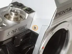
Remove two screws on either side of the lens mount.
-
-
-
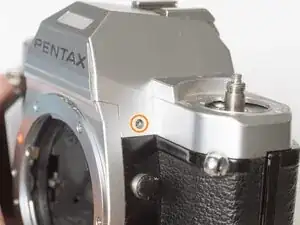
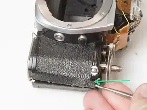
Remove one screw by the exposure compensation dial.
-
Use a spanner wrench to remove the lock nut under the advance lever.
-
Lift off the top cover slowly. It is still attached by one wire.
-
Unsolder one gray flash sync wire.
-
-
-
Use a nickel or other large coin to remove the hand grip.
-
Drip isopropyl alcohol along the edge of the leatherette to soften the adhesive.
-
Use a dull scraper to lift one corner and pull off the panel.
-
Repeat on the rewind side of the camera.
-
-
-
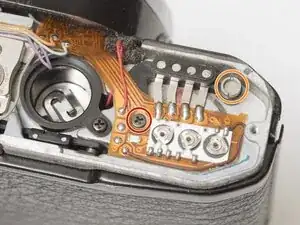
Remove one M1.7 x 4.5 mm screw.
-
Remove one slotted screw.
-
Use isopropyl alcohol to soften the adhesive under the flex PCB.
-
Gently lift the PCB until it is free from the camera body.
-
-
-
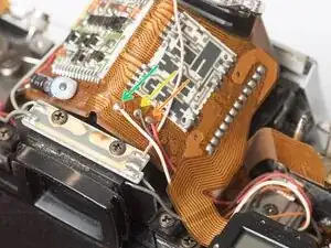
Unsolder one red wire.
-
Unsolder one light blue wire.
-
Unsolder one orange wire.
-
Unsolder one purple wire.
-
-
-
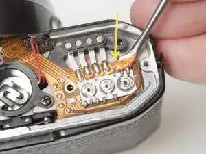
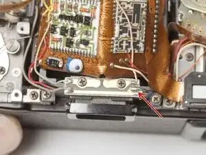
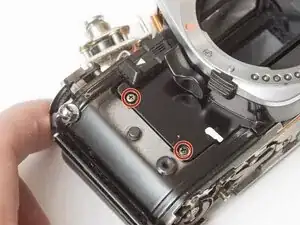
Remove one M1.7 x 4.5 mm screw.
-
Remove one M1.7 x 5 mm screw.
-
Remove one countersunk M1.7 x 5.5 mm screw.
-
Lift the contact terminal free from its seat.
-
Remove the tripod mount.
-
-
-
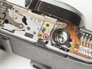
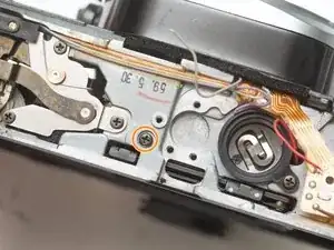
Remove one slotted screw.
-
Remove one M1.7 x 4 mm screw.
-
Loosen one slotted screw (this will remain connected to the assembly).
-
Lift the ISO resistor assembly off the rewind post. It is still attached by a flex PCB.
-
-
-
Remove one M1.7 x 2.5 mm screw. It is only accessible when the mode dial is in the 'L' position.
-
Remove one crosshead screw.
-
Lift the LCD out of the way. It is still attached by a flex PCB.
-
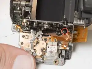
Remove one M1.7 x 2.5 mm screw.
-
Remove one slotted screw.
-
-
-
Unsolder one gray wire.
-
Unsolder one red wire.
-
Unsolder one brown wire.
-
Unsolder one white wire.
-
-
-
Wind the shutter
-
Make sure the mode dial unit and ISO selector unit are free from their mounting points.
-
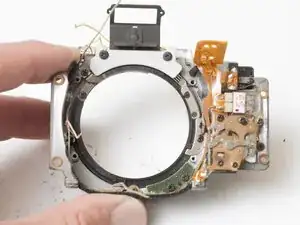
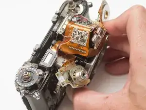
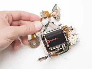
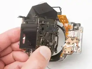
Wiggle the mirror box and front board free.
-
Watch for wire snags as you pull it free.
-
Check for loose shim washers on the front board and note their position.
-
-
-
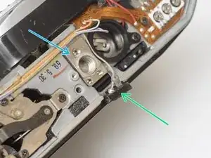
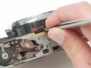
Shutter should be in the charged state.
-
Mirror box should be in released state.
-
Pay close attention to wire routing during install.
-
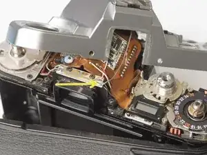
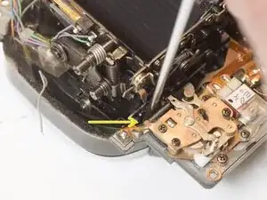
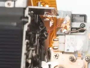
To test the actuation of the mirror and shutter, wind the camera, then insert a tool into this slot and push the release lever to the left.
-
-
-
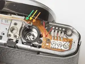
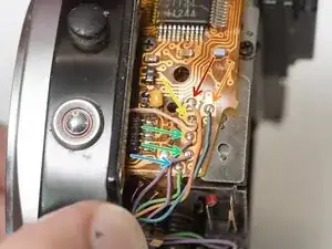
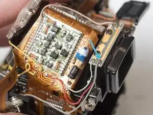
Unsolder one orange wire.
-
Unsolder one blue wire.
-
Unsolder one pink wire.
-
Unsolder two purple wires.
-
Unsolder one green wire.
-
-
-
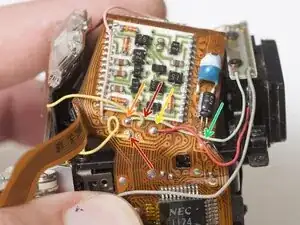
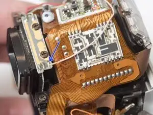
Unsolder two yellow wires for the aperture resistor.
-
Unsolder one gray wire for flash sync.
-
Unsolder one red wire for metering cell power.
-
Unsolder one black wire for metering cell power.
-
Unsolder one gray wire for flash sync.
-
Unsolder one pink wire for flash sync.
-
-
-
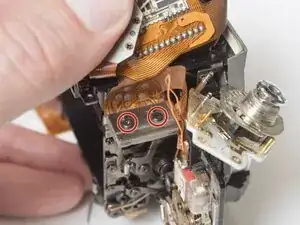
Remove two M1.4 x 2 mm screws.
-
Use a spudger to gently pry off the connector plate.
-
Remove the silicone insulating pad.
-
-
-
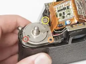
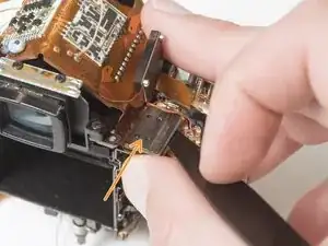
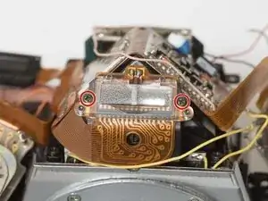
Remove one M1.7 x 4.5 mm screw.
-
Loosen one M1.7 x 4.5 mm screw but leave it in place.
-
Remove two M1.7 x 1.6 mm screws.
-
Remove the mirror governor.
-
Remove one plastic bushing.
-
-
-
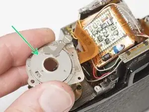
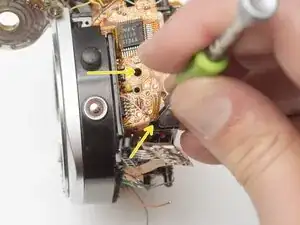
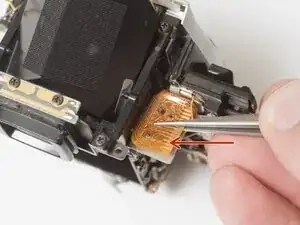
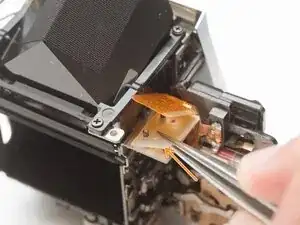
Gently lift away the PCB from the mirror box.
-
The TTL flash metering needs to be unseated from the housing to free the PCB for removal.
-
-
-
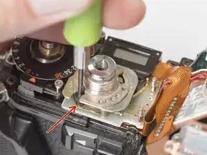
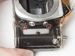
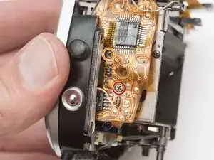
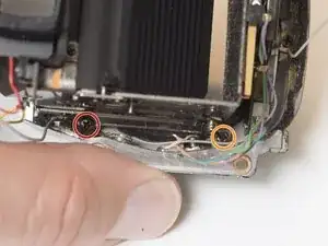
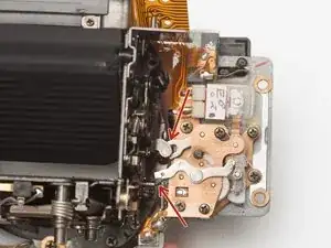
Remove two M2 x 3 mm screws.
-
Remove one M1.7 x 3 mm screw.
-
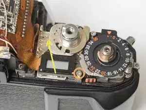
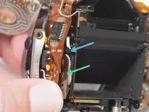
Charge and release the mirror so it is in the taking position (up against the focusing screen).
-
Remove one M1.7 x 3 mm screw.
-
-
-
Check the coupling points for the aperture control, depth of field preview and self-time when reassembling the mirror box.
-
To reassemble your device, follow these instructions in reverse order.