Introdução
A common failure of the Pentax MZ-S is the Mirror Drive Lever. This is a plastic lever on the side of the mirror box that moves the mirror up and down during an exposure. The plastic tip that follows the rotating cam can break off leaving the mirror stuck in the up position. The shutter should still fire normally but the mirror won't travel its full stroke. Additionally, with the mirror stuck, the viewfinder will appear black and the camera will not be able to autofocus.
This guide explains how to disassemble the camera to access the Mirror Drive Lever as well as how to install the new part to ensure proper functionality. A general understanding of how cameras work is recommended. Some technical soldering is also required.
-
-
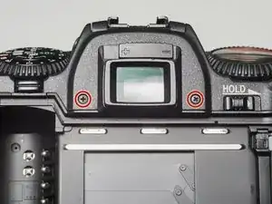
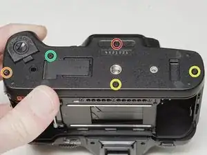
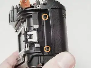
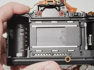
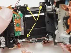
Remove two 7.5 mm #00 screws.
-
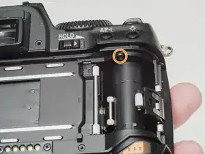
Remove one 9.0 mm #00 screw.
-
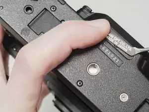
Remove one 13.5 mm #00 screw from inside the battery compartment.
-
-
-
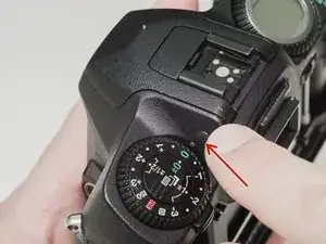
Push the button to pop up the flash.
-
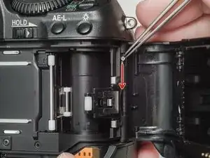
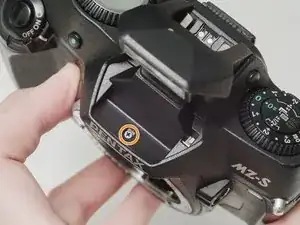
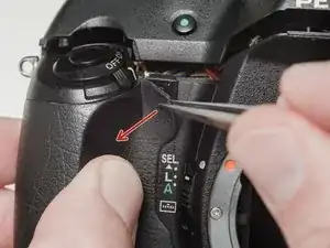
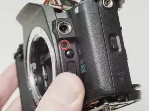
Remove one 3.5 mm #00 screw.
-
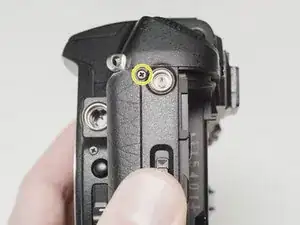
Remove one 5.5 mm #00 screw.
-
-
-
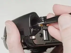
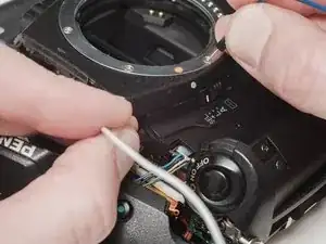
Use a 1kΩ-10kΩ high power resistor to discharge the capacitor. Place the resistor between the blue wire, exposed in the previous step, and ground.
-
-
-
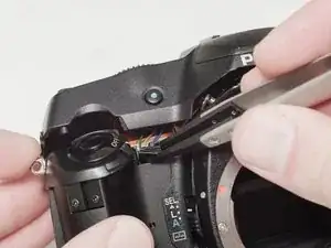
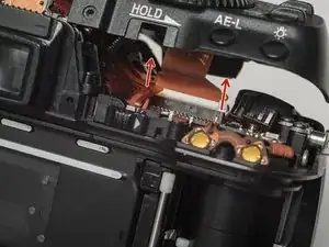
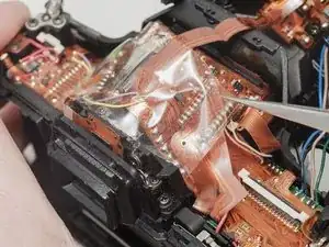
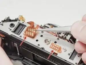
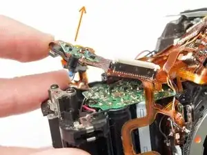
Remove the piece of cellophane tape covering the flex connections.
-
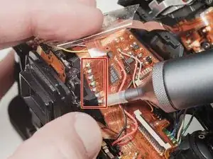
Desolder flex connetions.
-
-
-
Use isopropyl alcohol to soften the adhesive under the country plate and remove.
-
Remove one 5mm #00 screw.
-
Remove one 7.5mm #00 screw.
-
Remove two 4.5mm #00 screws.
-
Remove one 5.5mm #00 screw.
-
Remove the plastic frame around the accessory grip contacts.
-
-
-
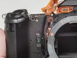
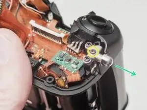
Remove one 6.0 mm #00 screw.
-
Remove two 3.5 mm #00 screws.
-
Remove one 5.0 mm #00 screw.
-
Remove the strap lug.
-
-
-
Carefully pull the right panel away from the body. It is still attached.
-
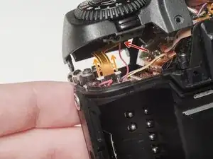
Desolder the flex connections.
-
-
-
Remove the protective mask around the accessory grip contacts.
-
Lift the flex contacts free of their retaining posts. Use isopropyl alcohol to soften any glue or tape that is present.
-
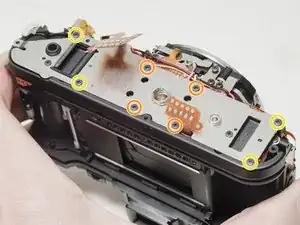
Remove four 4.0 mm #00 screws (standard metric threads).
-
Remove four 4.0 mm #00 screws (plastic threads).
-
-
-
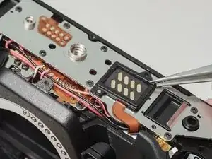
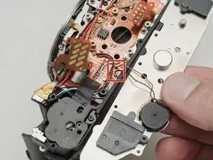
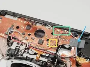
Desolder the white and pink wires.
-
Desolder the red, black and gray wires.
-
Desolder the red, black and orange wires.
-
Desolder the white and blue wires.
-
Carefully peal the tape away and detach the red, black, white and blue wires from the glue. Use isopropyl alcohol to soften the glue if necessary.
-
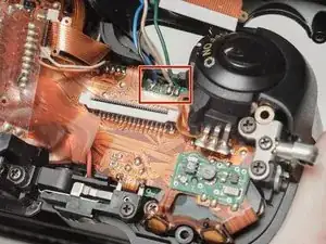
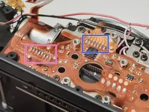
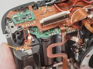
Desolder the flex connection.
-
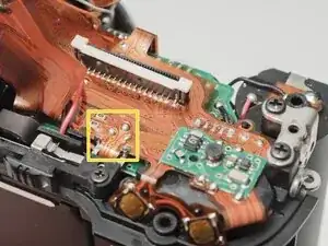
Desolder the flex connection.
-
-
-
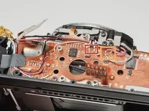
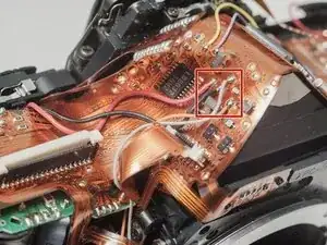
Desolder red, black, gray and orange wires.
-
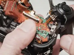
Desolder flex contacts.
-
Disconnect flex connector.
-
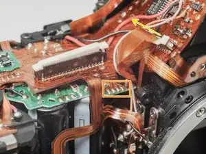
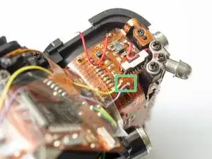
Desolder yellow and purple wires.
-
-
-
Desolder flex connection and remove from retention posts. Use isopropyl alcohol to soften the glue if necessary.
-
Carefully peal the flex cable from the surface of the flash capacitor. Use isopropyl alcohol to soften the glue if necessary.
-
-
-
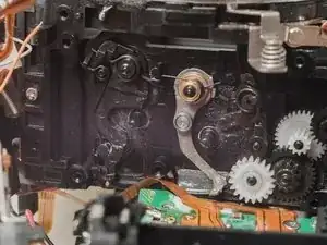
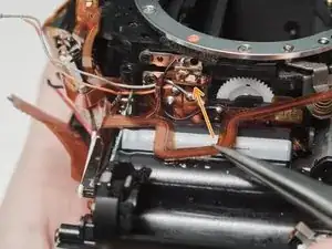
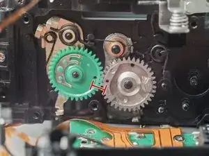
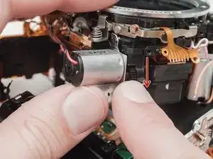
Rotate the black gear downward until the mirror flips up into the taking position. It may take several turns.
-
-
-
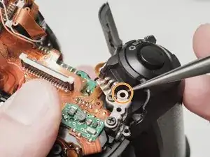
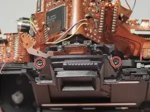
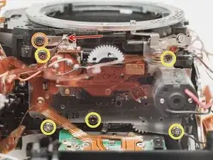
Remove two 6.5 mm #0 screws.
-
Remove one 8.0 mm #0 screw.
-
Remove one 4.0 mm #00 screw.
-
Remove one 4.5 mm #00 screw.
-
Remove two 2.5 mm #00 screws.
-
There may be a shim washer here. Remove if loose.
-
Remove one 4.0 mm #00 shoulder screw.
-
-
-
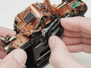
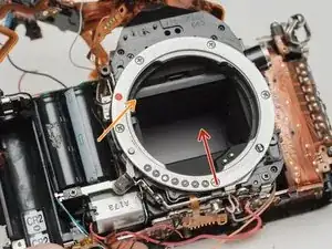
Push the mirror box up to free it from the bottom plate.
-
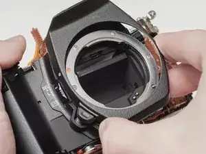
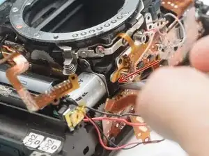
Lift the left side of the mirror box and rotate it up and out of the camera body.
-
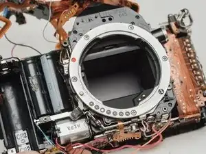
Check for shim washers at the mount locations. Note location and remove if loose.
-
-
-
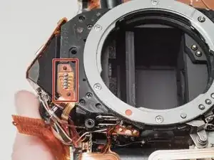
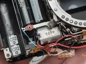
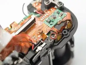
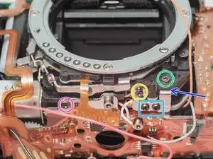
Desolder the black wire.
-
Remove one 3.0 mm #00 screw securing the mount LED.
-
Remove five 3.5 mm #00 screws.
-
-
-
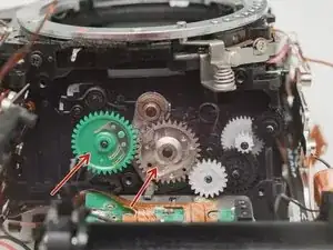
Remove two drive gears from the mirror box.
-
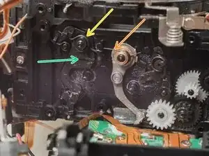
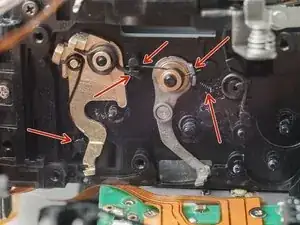
Remove shutter charge lever spring.
-
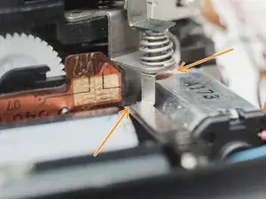
Remove mirror drive lever spring.
-
Remove mirror drive lever.
-
-
-
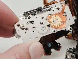
Transfer the two springs from the old drive lever to the new drive lever.
-
Install the new drive lever.
-
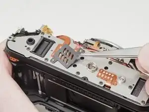
Check that all the bias springs are correctly tensioned against the indicated posts.
-
-
-
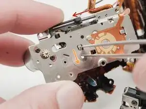
Slide the aperture actuator to the left.
-
Pinch the small lever downward and let it snap back into place.
-
The aperture actuator should be held in place on the left end of its travel if done correctly.
-
-
-
Install mirror motor plate.
-
Turn the black gear downward to move the mirror through a full cycle.
-
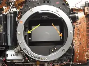
Check that the mirror comes all the way down onto the mirror rest when in the taking position.
-
Check that the aperture control mechanism is moving in its slot.
-
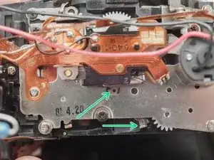
Continue turning the black gear until this hole appears in the opening and the shutter charge lever moves to the right.
-
-
-
Apply a low DC voltage (3-6 V) to the mirror motor to check the operation of the mirror box. Normal movement in the shutter blades, aperture control and mirror should be observable.
-
To reassemble your device, follow these instructions in reverse order. Be careful to route wires and flex cables in the way that they were originally assembled.
11 comentários
wow, this is not for the faint of heart!
Wow! Respect!!!
Wow!! respect!!!