Introdução

The process of removing covers and simple internal components requires minimal technical experience.

  1. sCvxASM2BTUNfVMf
    sCvxASM2BTUNfVMf
    EtLwhCRCqonNEGSk
    • Unplug the device from any energy sources.

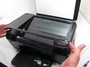
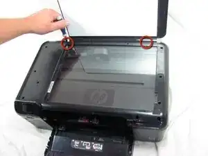
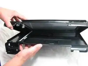
    • Lift the top cover of the scanner.

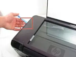
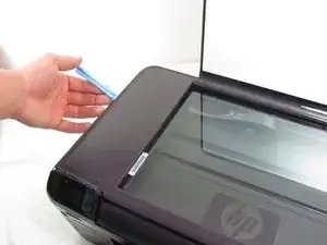
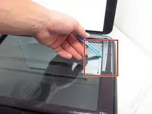
    • Use a plastic opening tool to remove the plastic frame surrounding the glass.

  2. VNrMdR6aSSgpgFKy
    • Carefully pull the frame away from the glass.

    • If it doesn't remove easily, use the iFixit Opening Tool again to pry stuck sections.

    I found it too difficult to unclip using a pry tool at the front edge. However as far as I can see, unless you need to replace the glass this surround can stay on place - there are no screws holding the shell together under the frame.

    Dr_T -

  3. La4NjOYFGpuEGHdT
    • Use a T10 screwdriver to unscrew the two screws that fasten the frame to the printer hood.

  4. VZVQv5DxD6Q6xkwE
    VZVQv5DxD6Q6xkwE
    xCmMqeCQodwRBHpy
    • Put your finger behind the panel with the power button.

    • Then, pull the piece outwards.

    Note that: 1) there's a sprung clip behind, which you need to release - don't just pull!; and 2) the panel is held in by tabs on the left hand side, so it comes out with a rotation of the right side towards you.

    Dr_T -

  5. 4IgJZ636eEnD1oEA
    4IgJZ636eEnD1oEA
    H4Oqgq6LxkTpGZWT
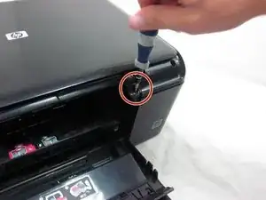
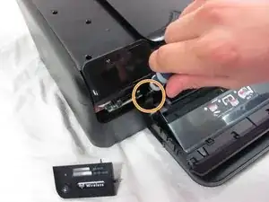
    • Unscrew the screw inside the power button panel space.

    • Then, unscrew the screw that is across the printer slider.

  6. R5ROP3WPApla5nps
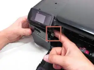
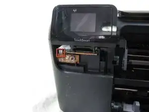
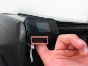
    • Pull the white circuit board outwards which is located under the small screen.

    • Unplug the small ribbon cable from the circuit board.

    • Be careful when you unplug the ribbon cable not to use too much force. Using too much force may damage or rip the cable.

    This is the small board with the on/off switch and an LED on it - it is brown, not white, in my own printer.

    Dr_T -

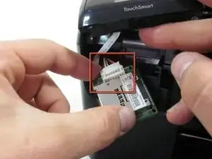
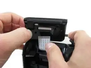
    • Unplug the small ribbon cable from the circuit board. Be careful when you unplug the ribbon cable not to use too much force. Using too much force may damage or rip the cable.

  7. KX5A1MUNrSRLJLMS
    KX5A1MUNrSRLJLMS
    BweAaTKHfGHwQZTQ
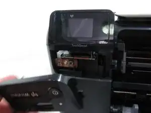
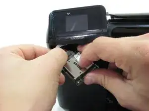
    • Pull the memory card reader's circuit board out.

    • Detach the white wiring connector from the back of the circuit board.

    • You may need to use a finger nail or a plastic opening tool to detach the white wiring connector from the circuit board.

  8. DhRjmbr3bJtfSrK1
    DhRjmbr3bJtfSrK1
    U54hLGXlQGpDuGSr
    • Put your finger behind the small screen.

    • Then, pull it up.

    • Do not hesitate to use force to remove the TouchSmart panel.

    • Disconnect the ribbon cable from the small screen.

    The screen, and the memory card reader module, do not have to come out to release the top cover, so depending on what you want access to you could leave them, and the small switch PCB, in place.

    Dr_T -

  9. LCqFTKjM3obx4CaN
    • Pull the printer hood upward.

Conclusão

To reassemble, simply follow the steps in reverse order.

Renee Lamb

Membro desde: 26/09/12

244 Reputação

3 comentários

Excellent helpful easy to follow instructions. Thanks.

In step 7, removal of the Touch Pad, I was not able to locate the release clip. Feeling around, what I thought was the latch was a ribbon cable that I distorted but didn't destroy. The top came off without the Touch Pad removal. Once the top was off, I located a latch on the back right of the Touch Pad, but once released, it didn't help to free up the Touch Pad. I couldn't get the Touch Pad off.

Ken -

Really great to have these instructions, just what I needed so that I could open up my printer.

Thanks!

Dr_T -

Replying to Ken: I couldn't get it out either. I carried on to get the top cover off without removing it. I think I may have seen a screw in behind the touch pad / display? Certainly a clip, at least.

Dr_T -