Introdução
Follow this guide to replace a broken or faulty circuit board in your Nintendo Switch dock.
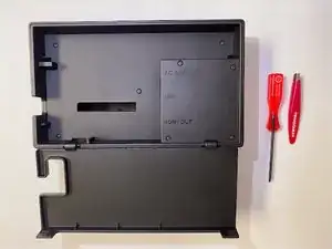
Required Tools: Tri-head 360x50 or Y00 driver, mini-tweezers, needle-nose pliers
-
-
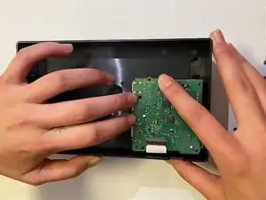
Remove the Switch from the dock
-
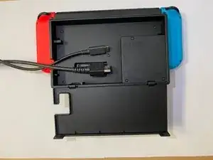
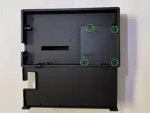
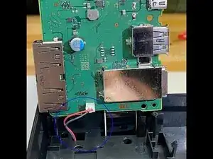
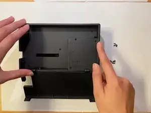
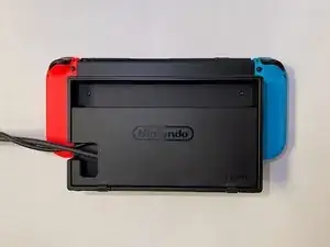
Orient the dock so that the adapter block faces up like shown
-
-
-
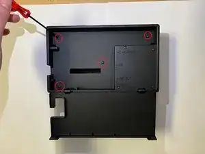
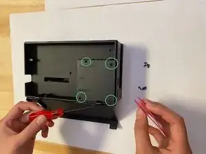
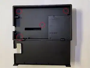
Using Tri-head 360x50 (or Y00) driver, unscrew the next four screws shown (A, B, C, D) and use the mini-tweezers to remove the screws. These screws will be longer.
-
Place the screws in a secure location.
-
-
-
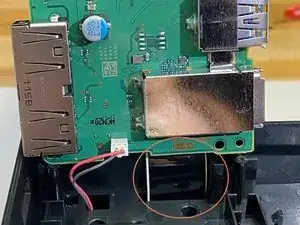
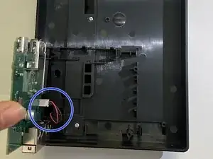
Carefully unplug the red and black cable connecting the circuit board with the dock housing
-
This cable can be more easily removed with a pair of needle-nosed pliers. Clamp on to the plastic casing and gently pull to remove the cable
-
-
-
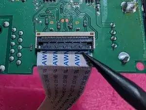
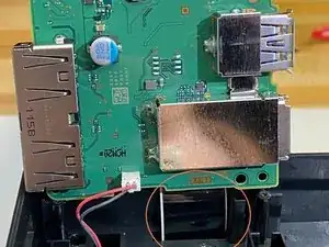
Gently pull the film cable out of the circuit board. The cable should slide free when lightly pulled.Don't pull on it, you're liable to break the cable or connector. -
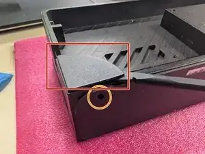
Instead, look at the connector itself. There's a flap (second photo) on the top side of the connector. Using a spudger or fingernail (NO METAL - if you tear the cable, nothing will work and you'll be very sad) to pop up that flap. It's a locking mechanism, so there's a bit of resistance.
-
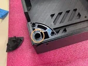
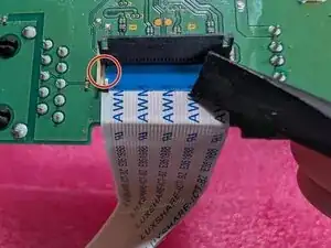
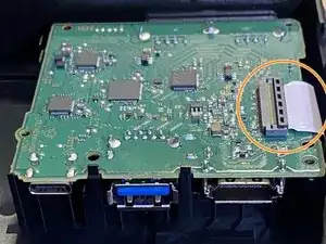
Once you've lifted the flap up, take a note of the orientation of the cable and how it sits in the connector. The cable has two tabs, on one the right and one on the left (marked with a red circle), which align the cable in the connector. Good idea to take a photo at this step for reference later.
-
The cable can then be gently lifted (to get the tabs out of their alignment grooves) and pulled back away from the connector to release it. Close the locking latch so it doesn't break off later.
-
-
-
Carefully reconnect the film cable to the replacement circuit board.
The cable should slide in when gentle pressure is applied.Lift the locking flap (see step 7 for images) with a plastic (NO METAL) tool or your fingernail, slide the cable in and make sure the tabs are seated properly before closing the locking latch. -
Ensure the cable is oriented correctly before insertion to avoid damage.
-
-
-
Make sure the cable is oriented correctly - you can check the port to make sure the holes will line up correctly
-
Align plug - end of cable to port and apply gentle pressure. The cable should slide back into place.
-
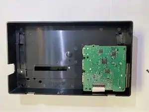
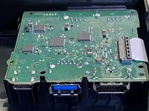
The circuit board should fit without obstruction.
-
-
-
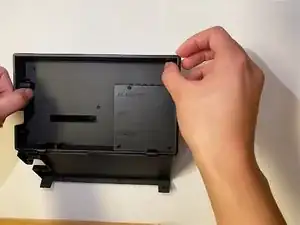
Place backing onto dock. All screw holes should line up.
-
Apply gentle pressure. (You should feel a slight "give" as it seats properly)
-
-
-
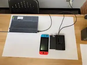
Plug HDMI cable into a device with an HDMI port (TV, monitor, computer, etc.) (NOTE: need adapter for PC for video and audio connection)
-
-
-
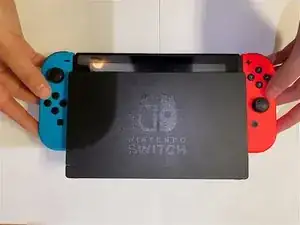
Insert Nintendo Switch into dock and turn it on.
-
The dock should charge your switch. If it doesn't, check the power supply/power cable
-
When correctly seated in the dock, the Switch screen will remain black
-
-
-
Use Switch normally to test audio and video output
-
If Switch works normally but the dock doesn't, check to make sure the following are true:
-
Both cables are plugged in correctly
-
Both cables are not obstructed or damaged
-
Circuit board is not damaged
-
Circuit board seats correctly into housing
-
All electrical equipment should be stored safely out of the way of hazards. After replacement, the Switch Dock should function properly.
6 comentários
At https://www.hollywood-docks.com, we specialize in new dock installations, existing dock repairs and updates, seawall installations and repairs, deck and patio construction, and much more. We pride ourselves on providing high-quality craftsmanship and exceptional customer service.
Wrong kind of dock, bro.
modtang -
had a bad surge and now dock isn't working (but the power cord will charge the switch directly)
how do I tell if it is the circuit board or the USBC board that is bad?
Jeff -