Introdução

  1. yUINxtt2JccXMRVi
    yUINxtt2JccXMRVi
    3Zd1HTvIDHjLBsOb
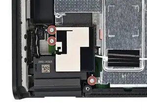
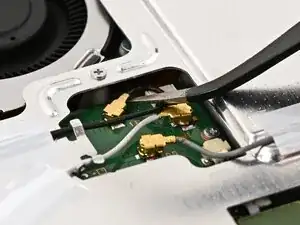
    • Use a JIS 00 driver to remove the three 4.4 mm‑long silver screws securing the lower antenna.

  2. 5RpO5GQji44FWCUr
    5RpO5GQji44FWCUr
    pRipdAlsxjSJXDmB
    • Use tweezers or your fingers to remove the lower antenna.

  3. jC53BveXKEYEqlUI
    jC53BveXKEYEqlUI
    sAYFyvwHGPeFMywp
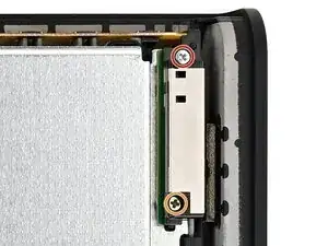
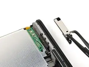
    • Use a JIS 00 driver to remove the two screws securing the upper antenna:

    • One 4.4 mm‑long silver screw

    • One 4.6 mm‑long green screw

  4. bGWBESkLk54DPEUw
    bGWBESkLk54DPEUw
    BZRDRtoNkxSUeDkK
    • Use tweezers or your fingers to remove the upper antenna.

  5. JYawFZ2fAjORiCTh
    JYawFZ2fAjORiCTh
    MIb4NWZKsMPGeBv3
    SHORs4ixoADsjAbX
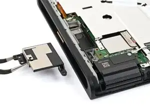
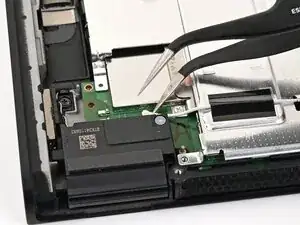
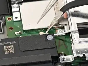
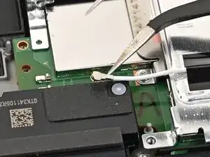
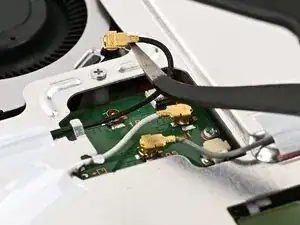
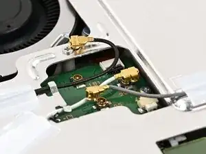
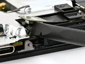
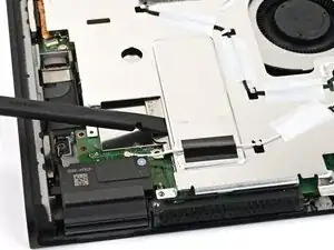
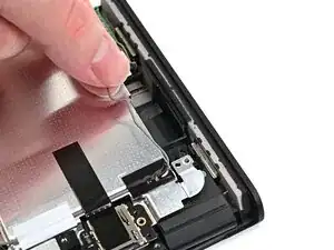
    • Insert an arm of angled tweezers under the metal neck of the white interconnect cable coaxial connector (located beneath the lower antenna) and lift straight up to disconnect it.

  6. 6rGSkmqlwFRHwhn2
    6rGSkmqlwFRHwhn2
    ObCwAQPFAcQvjyC1
    JBKvGj1X4OaKhkTg
    • Repeat this procedure to disconnect the three central coaxial connectors from the board.

  7. BtXyRdmtfmwHfyE3
    BtXyRdmtfmwHfyE3
    hxaMIZVcj6APPP1k
    Q13OE4tSMvxpmuwA
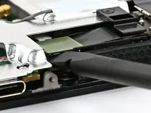
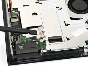
    • Use the flat end of a spudger to pry up and disconnect the MicroSD card reader press connector, located next to the bottom USB‑C port.

  8. bqpoQgshqObqk5KS
    bqpoQgshqObqk5KS
    HayjKJVgRNi4wsoo
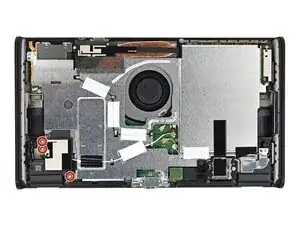
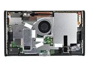
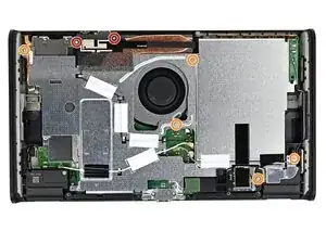
    • Use a JIS 00 driver to remove the seven screws securing the shield plate:

    • Two 6.2 mm‑long silver screws

    • Five 4.4 mm‑long silver screws

  9. V3w363uMCVAgIbCw
    V3w363uMCVAgIbCw
    6MGPPF63BbMhVDMp
    HBpyqYLfivWONNgf
    • Insert the flat end of a spudger between the shield plate and the processor's heat sink, next to the square (⛶) marking on the shield plate.

    • Twist the spudger to lift the shield plate and separate the thermal putty bonded to it. Keep lifting the shield plate until you don't feel resistance.

  10. MjfijmcCnISrMyBJ
    MjfijmcCnISrMyBJ
    QW3Bfoix1WgRqNLD
    QdnpOBHaba52xkcB
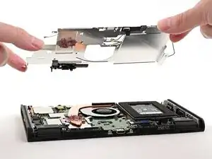
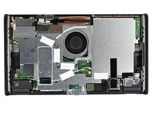
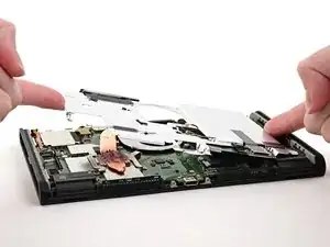
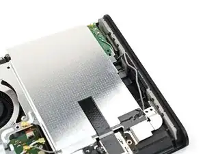
    • Lift the left edge of the shield plate to ensure it's fully separated from the thermal putty.

    • Gently set the shield plate back down.

  11. JBhpxTJNtwAdCiYs
    JBhpxTJNtwAdCiYs
    2ilKrxE4yHCDGpS1
    rukRxG3qWsJwlE2N
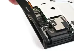
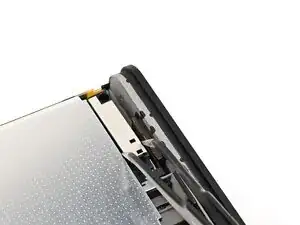
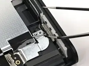
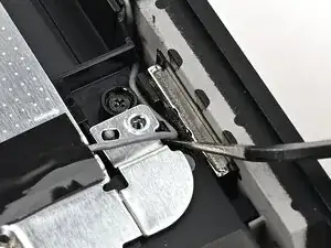
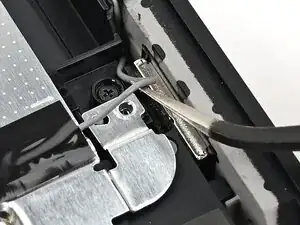
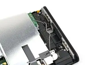
    • Insert one arm of angled tweezers underneath the gray antenna cable at the bottom-right corner of the console.

    • Lift the cable out of the black clip securing it to the frame.

  12. P6O6YGUEKW1OJdSk
    P6O6YGUEKW1OJdSk
    DyDJTVrhdclhCHWK
    iCLA4uhQPBRsDH1e
    • Unroute the gray antenna cable from its channel along the right edge of the console.

  13. MRYYVyKo2rD3LmAQ
    MRYYVyKo2rD3LmAQ
    xPS41OHOvOEYFKVP
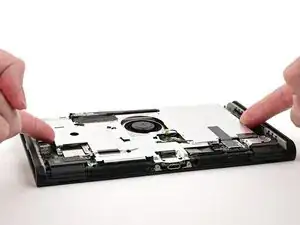
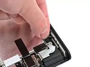
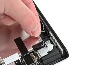
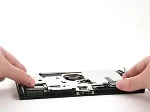
    • Lift and slide the shield plate away from the right edge of the console until the gray antenna cable is completely free.

  14. SCkg4gMqMOo5UCZe
    SCkg4gMqMOo5UCZe
    CjnnRkpCrujacoSG
    • Pick up and remove the shield plate.

Conclusão

To reassemble your device, follow these instructions in reverse order.

Nick Schultz

Membro desde: 24/03/24

45909 Reputação

0 comentários