Introdução

Follow this guide to replace the hinges in a Nintendo Switch 2 game console.

The Switch 2 uses JIS screws. If you use a non-iFixit Phillips driver in JIS screws, you'll risk stripping them. iFixit's Phillips bits are designed to be compatible with JIS screws.

  1. NQsFgQ1fC1wBuILk
    NQsFgQ1fC1wBuILk
    k2pFyTPIZxMXGMcY
    mgVMJXcfpXGxpxvI
    • For your safety, discharge the battery below 25% before disassembling the console. This reduces the risk of a fire if the battery is damaged during the repair. If the battery is swollen, take appropriate precautions.

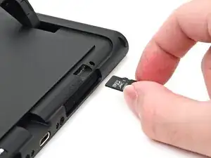
    • Remove any game cards and disconnect any cables, controllers, or other accessories from the console.

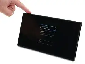
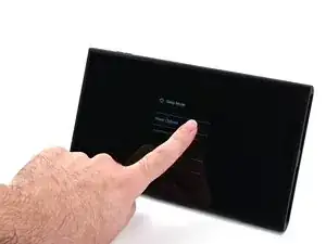
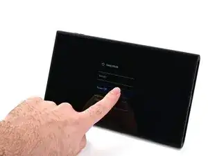
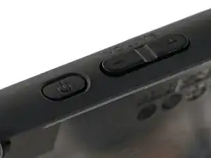
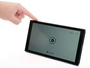
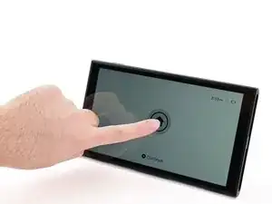
    • Power off the console by holding down the power button, selecting Power Options, then pressing Power Off.

  2. 5YVNpBaCsqgshIAj
    5YVNpBaCsqgshIAj
    GKJalBLCUFb4sFLQ
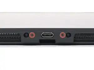
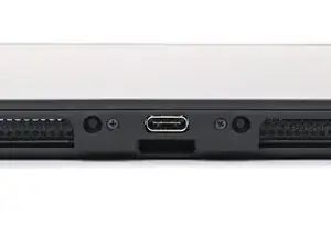
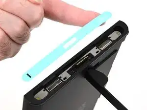
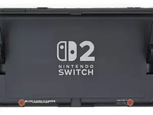
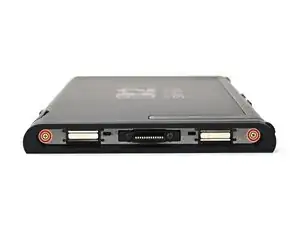
    • Use a JIS 00 driver to remove the two 3.1 mm‑long screws on either side of the bottom USB-C port.

    • You can try a non-iFixit Phillips driver in a pinch, but you risk damaging or stripping the screw. Push down firmly on the driver and twist slowly.

  3. jlL63CHmnGBMytYI
    jlL63CHmnGBMytYI
    we1DAds4sRAvig3L
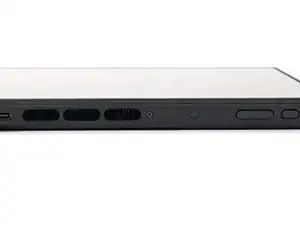
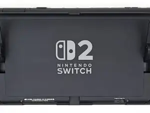
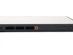
    • Use a JIS 00 driver to remove the 3.1 mm‑long screw on the top edge of the console (next to the ventilation cutouts).

  4. bZVWHoC1W1mgYUh6
    • The Switch 2 has stickers on either side that need to removed to access the screws securing the back cover. It's easy to damage the stickers during removal, but you can mitigate this by regularly reheating the stickers and working carefully.

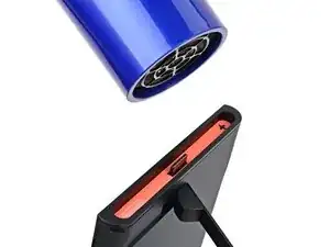
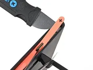
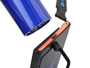
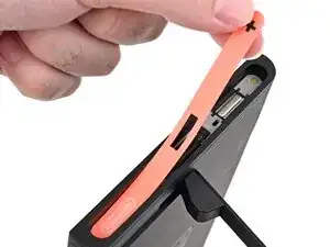
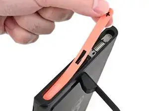
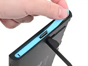
    • Use a hair dryer or heat gun to heat the sticker on the right side of the console, labeled with a "+" symbol, until it's hot to the touch.

    • You can use the kickstand to prop the console up vertically for easier access.

    • If you're using a heat gun, set it to low to avoid melting the plastic edge of the console.

  5. OKUSRtVWgoTdIJHM
    OKUSRtVWgoTdIJHM
    ao4XkPrFUXVEwjnE
    BBVFo3I2R5OkIAaO
    • The pointed end of the tweezers can damage the sticker from the underside, leaving a noticeable mark. If it's difficult to lift, apply more heat instead of using more force.

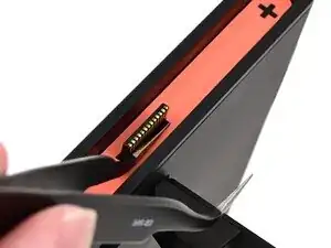
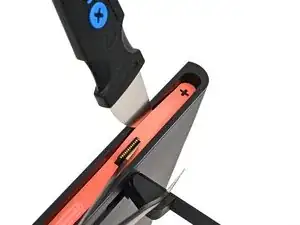
    • Slide one arm of angled tweezers underneath the sticker from its cutout around the right Joy‑Con 2 connector.

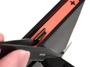
    • Gently pry up on the sticker until it starts to lift from the console.

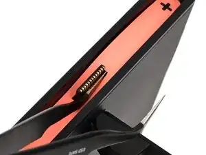
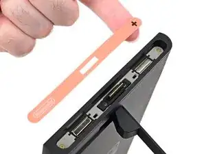
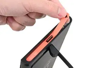
    • Leave the tweezers in place to keep the sticker lifted.

  6. SSHxFVejMfpHGJA2
    SSHxFVejMfpHGJA2
    J1QBmuIPqd6MFrTw
    SXBJ1O1ugK2pY1BA
    • Insert the tip of a Jimmy into the gap formed between the long edge of the console and the sticker.

    • Gently pry up the sticker, working your way up the long edge until the top of the sticker is separated from the console.

    • Remove the tweezers once the sticker is lifted.

    • You can leave the Jimmy in place to hold the top of the sticker off the frame—if it falls back into its recess, repeat this procedure to lift it back up.

  7. wjdVrm2URbcSArBQ
    • Reheat the bottom of the right side until it's hot to the touch.

  8. vJxKQYyTutICrubh
    vJxKQYyTutICrubh
    TJPcnDmIZj1EuXPM
    PYVXYyNYBH45MwPn
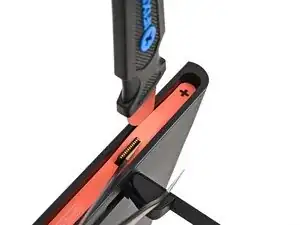
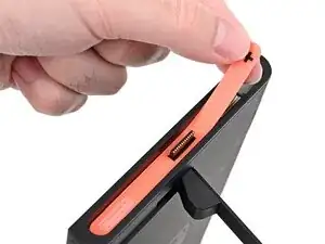
    • Carefully lift the sticker over the Joy‑Con 2 connector, then peel it up fully to remove it.

  9. 4JgLYAUkBPKHYL5N
    4JgLYAUkBPKHYL5N
    QdPU16ygx5WaXIOv
    Xt2DD4nGwtT11WTm
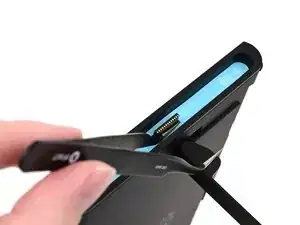
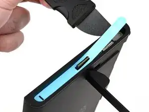
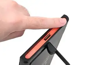
    • Repeat this procedure to remove the sticker along the left side of the console, labeled with a "-" symbol.

  10. QVVJCYqdQNmEJSpX
    QVVJCYqdQNmEJSpX
    scvilok6pD5gCZvZ
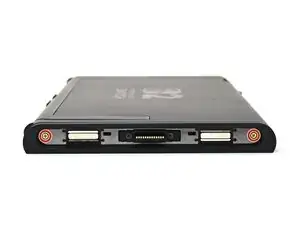
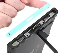
    • Use a JIS 00 driver to remove the two 3.6 mm‑long gold screws on each side of the console (four in total).

  11. 6i3X4ALKCNjQSqSD
    6i3X4ALKCNjQSqSD
    NP4lX6nYvxKhTfTQ
    RaITkR2vdQGZxRiP
    • Use your fingers to flip up the kickstand on the back of the console.

    • If there's a microSD Express card installed, remove it now before you continue to the next step.

  12. lFPPWotqhiCQDcvj
    lFPPWotqhiCQDcvj
    wiEGCoNC1dmsRgIJ
    • Use a Y00 driver to remove the two 4.4 mm‑long screws in the kickstand cutout.

  13. JoHeqQiUYhLrECIv
    JoHeqQiUYhLrECIv
    jUrqv1dwQQCgGxyb
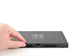
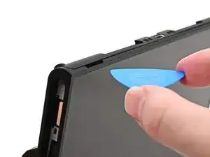
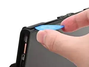
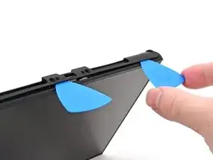
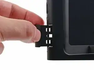
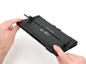
    • Insert an opening pick into the gap between the back cover and speaker cutout on the bottom edge of the console.

  14. cfJBwTZgEEalAn1Q
    cfJBwTZgEEalAn1Q
    IaF3XLZP3SpincUb
    • Slide the opening pick towards the USB-C port until it's underneath the screw hole next to the port.

  15. Ef3HiXgUlqP42rES
    Ef3HiXgUlqP42rES
    ETDCZYoSnOKTK13P
    qThFHMcpbOd31vL1
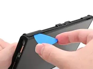
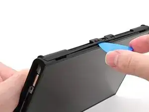
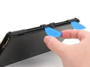
    • Insert a second opening pick underneath the screw hole on the opposite side of the USB-C port, and slide it to the corner of the console.

  16. 1vMRiPFOONkGwlZm
    1vMRiPFOONkGwlZm
    QqNvCOWsKavoX6mC
    • Slide the first opening pick back to where it was first inserted.

  17. wrN6QkEAU3sY5CFG
    wrN6QkEAU3sY5CFG
    mUqGchwWQVXF2eXE
    XVWaUHWhVCdPAXTI
    • Be careful not to drop your console. Once the back cover pops up, the opening picks will fall out of place.

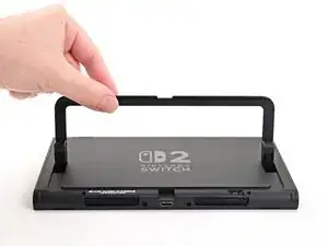
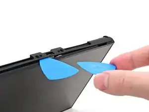
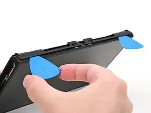
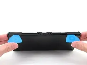
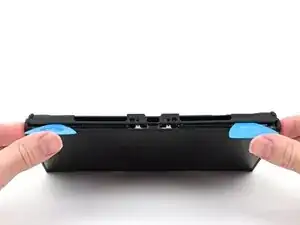
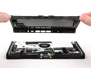
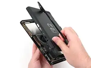
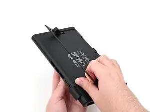
    • Hold the console with two hands. Rest your thumbs on the opening picks.

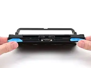
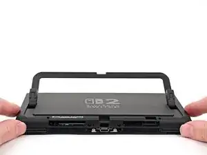
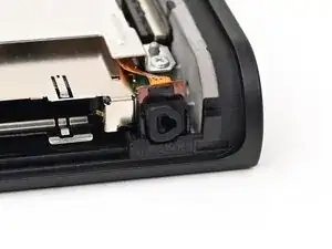
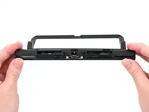
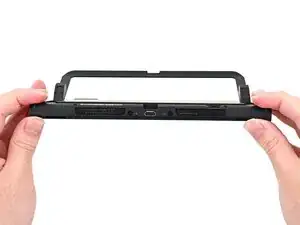
    • Push up on the opening picks to lift the back cover until it pops up above the USB-C port.

  18. OfZYXVPDOPAdKZpY
    OfZYXVPDOPAdKZpY
    H1krkBLPGZNL4OFd
    by4KabwvvEnPDlPP
    • Lift the back cover up from the bottom edge and remove it.

  19. DfILd4MaTGsG2OPa
    DfILd4MaTGsG2OPa
    ysnQLvyUGsRUX5Ta
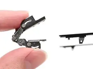
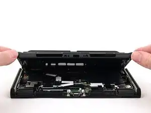
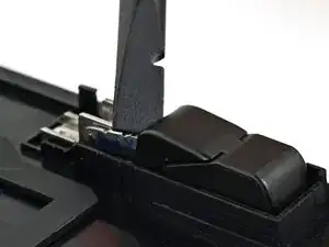
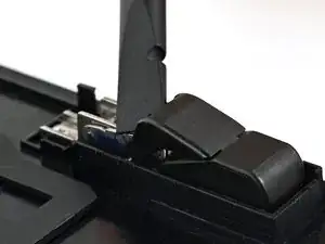
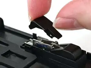
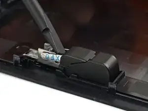
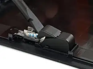
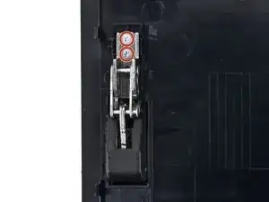
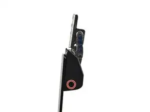
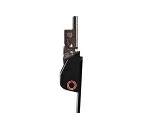
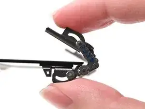
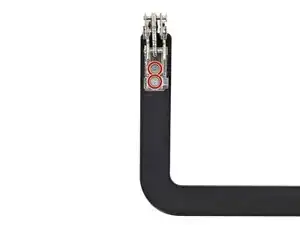
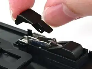
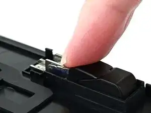
    • Use the flat end of a spudger to pry up one of the hinge's plastic upper hinge covers until it "pops" up.

  20. wIyXyfCsxSt3AmQk
    wIyXyfCsxSt3AmQk
    rP1M4gDDORYrGGJT
    • Pull the upper hinge cover out from underneath the lower hinge cover to remove it.

    • The cover is clipped in place and requires a little bit of force to remove.

  21. 4bSJdJMnK5TBVgWu
    4bSJdJMnK5TBVgWu
    HCWbHGXj14iSrvH6
    hh2P5dES2SYbwrTC
    • Repeat this process to remove the upper hinge cover on the other hinge.

  22. BNQGyGdskvjUpMjR
    BNQGyGdskvjUpMjR
    RhpCMo3BvKWg1ivK
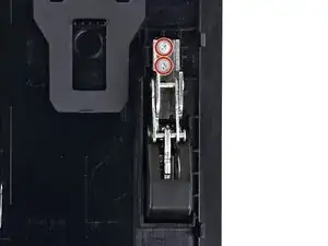
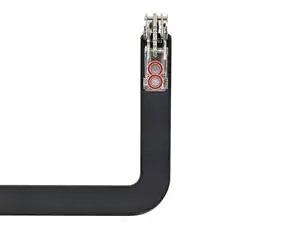
    • Use a JIS 00 driver to remove the two 2.3 mm‑long silver screws securing each hinge to the inside of the back cover (four total).

  23. OfqnhH3PUGsObFUm
    OfqnhH3PUGsObFUm
    M52V2iAoNQe12a5q
    LyVhOtSW2vWNJYkI
    • Open the kickstand to a 45‑degree angle and pull it out of the back cover to remove it.

  24. OHOAnZl2ICTqkQre
    OHOAnZl2ICTqkQre
    vrlSpp1BkfdQsXqp
    • Use a JIS 00 driver to remove the 1.7 mm‑long black screw securing each hinge cover to the kickstand (two screws total).

  25. uVs5Rr2KZRfeoF4b
    uVs5Rr2KZRfeoF4b
    YtGd3WrVCeKaxapm
    UmVymUUfBm3AQBvy
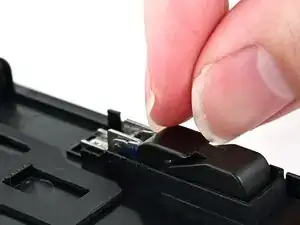
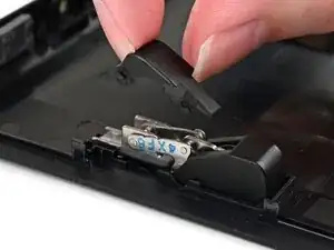
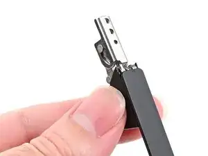
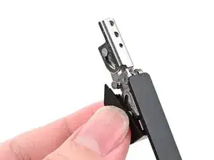
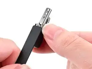
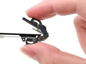
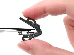
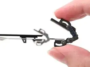
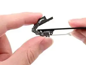
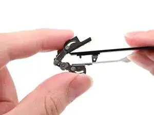
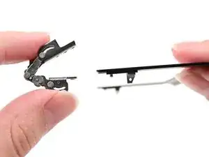
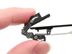
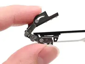
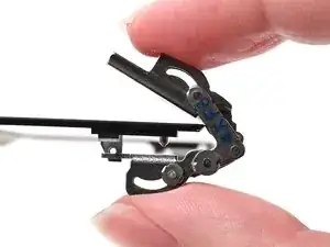
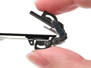
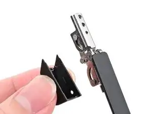
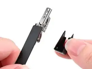
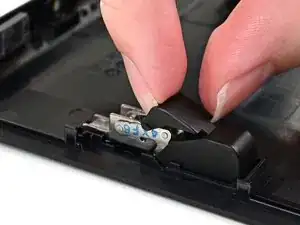
    • Use your fingers to pull one of the hinge covers at a downward angle away from its hinge to remove it.

  26. ZAZtTcuC1EFyWdDF
    ZAZtTcuC1EFyWdDF
    fKEZlYYDZrcJevQQ
    mYDdooRJbCRoRJCj
    • Repeat this process to pull the hinge cover off the other hinge.

  27. yVKOMPUnNVVRIjDQ
    yVKOMPUnNVVRIjDQ
    CXRyfTYAK1Ekxvvx
    FmhuQbLNCQBJFB1e
    • Use your fingers to fold both hinges as far back as they'll go.

  28. 2K6FGQQitSUgOtqn
    2K6FGQQitSUgOtqn
    Mw1F6mhYKUVoV34y
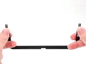
    • Use a JIS 00 driver to remove the two 2.3 mm‑long silver screws securing each hinge to the kickstand (four screws in total).

  29. Fhy5M62rOFV1mEBl
    Fhy5M62rOFV1mEBl
    ilEpQVLCZT2aNZqM
    261wlvuHJjNZWBOn
    • Lift one of the hinges off its alignment peg on the kickstand to remove it.

  30. qf6voXoeNWhJuHqt
    qf6voXoeNWhJuHqt
    wGmioJmgMV1sd6Ty
    T4kHpynytxSlNyfL
    • Repeat this process to remove the other hinge.

  31. joqvyGxvAljqRWdk
    • Congratulations on completing disassembly! The remaining steps will show how to reassemble your console.

  32. CDX2pZfVtDPuZXO1
    CDX2pZfVtDPuZXO1
    ECGIkMdRUHNQpiG6
    CXaSSNVZGcJk6o5t
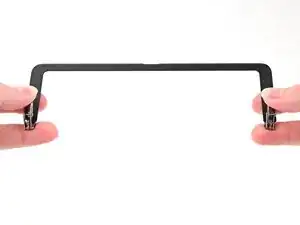
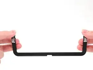
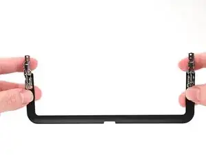
    • Align one of the hinges with its alignment peg on the kickstand and set it into place.

    • Use a JIS 00 driver to install the two 2.3 mm‑long silver screws securing the hinge.

  33. bfvqWOUoXTF6GtWL
    bfvqWOUoXTF6GtWL
    ypeEOBhOLT4IkZLO
    dIv1jLaUrijfe6tr
    • Align the other hinge with its alignment peg on the kickstand and set it into place.

    • Use a JIS 00 driver to install the two 2.3 mm‑long silver screws securing the hinge.

  34. QBEPWtnpfmyKvR2P
    QBEPWtnpfmyKvR2P
    WEKjayVEsvAvLTUu
    • Use your fingers to pull the hinges open until they're fully straight.

  35. uJrb4aqVOOx6Zndh
    uJrb4aqVOOx6Zndh
    bZOoUF6qQJWfe4qN
    xywBTFwYPpfveaaT
    • Align one of the hinge covers with its respective hinge and press it into place.

  36. xZbpRSNwwkelTI6V
    xZbpRSNwwkelTI6V
    LgyJTgj1QFCOLmAl
    shexvsPTVsHgDOHv
    • Repeat this process for the other hinge cover.

  37. YTy1n6DZxgNIfbTf
    YTy1n6DZxgNIfbTf
    soCtS2ByAAup14VN
    • Use a JIS 00 driver to install the 1.7 mm‑long black screw securing each hinge cover to the kickstand (two screws total).

  38. KCdxcENRKmZafv5b
    KCdxcENRKmZafv5b
    kEZOunUQFGI1d5VT
    L4BbGhghQXj166wh
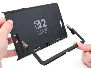
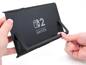
    • Align the kickstand so its hinge covers are facing the back cover.

    • Insert the hinges through their slots in the back cover and set the kickstand into its cutout.

  39. 4qNRWOeO6HU5a5WT
    4qNRWOeO6HU5a5WT
    mLjylE4XAmge2AaR
    • Use a JIS 00 driver to install the two 2.3 mm‑long silver screws securing each hinge to the inside of the back cover (four total).

  40. HsAZSfAPuvuV35Vm
    HsAZSfAPuvuV35Vm
    Uo6VYK5WDwb4KcEY
    Ma6imy6EZXFYCJr6
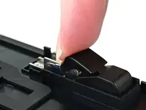
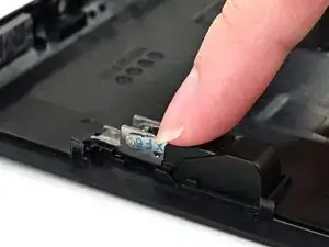
    • Align one of the upper hinge covers with its respective hinge, and slide it underneath the lower hinge cover.

    • Use your finger to press the upper hinge cover down until it clicks into place.

  41. haqO2KdnUpTWOmPx
    haqO2KdnUpTWOmPx
    sbTmVI4wRYHAGwvp
    SvBVefJ11wMq2Zfi
    • Repeat this process to install the other upper hinge cover.

  42. pjGoYIMeLVmy1UvQ
    pjGoYIMeLVmy1UvQ
    3QuAVGxoVkLJAutr
    XaA2wtFDKsCKjpGW
    • Fully pull out the game card tray.

    • Double-check the power and volume buttons to ensure they're seated correctly. If the rubber membrane beneath the buttons is out of place, ensure it's aligned with its pegs.

    • Check the microphone to ensure it's fully seated in its slot in the frame.

  43. sSyULZE5yvE6kQLS
    sSyULZE5yvE6kQLS
    aKWKHfsLgGKvrZRp
    LmvcHTVaG3uF1BnZ
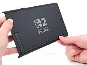
    • Align the top of the back cover with the top of the console.

    • Set the top edge of the back cover into place, checking the buttons and ports to ensure they're aligned properly. If they aren't, lift the back cover and try again.

    • Press along the top edge to fasten the clips securing the back cover to the console.

  44. DT64xZbXdxJfjZYW
    DT64xZbXdxJfjZYW
    PKuZdnNTaT1cvy2V
    • Squeeze the rest of the back cover and console together to fasten the clips.

  45. RnlwvPPTcBxlp3Mc
    RnlwvPPTcBxlp3Mc
    gQEivitJcMgvO6hy
    5R1bMuQkx6bZWrNa
    • Use a JIS 00 driver to install the three 3.1 mm‑long screws securing the back cover: one on the top edge of the console, and two on either side of the bottom USB-C port.

    • Use a Y00 driver to install the two 4.4 mm‑long screws in the kickstand cutout.

  46. cZ2jKSfXSxgXEuQL
    cZ2jKSfXSxgXEuQL
    Aob1o2jGToYPQD1q
    • Install the two 3.6 mm‑long gold screws on each side of the console (four in total).

  47. SAON1nUn2dJvZvWO
    SAON1nUn2dJvZvWO
    YsnER4viWUJvbNV5
    • Power on the console and test functionality to ensure it's working as expected.

  48. x1YrSApBUaLMVSjQ
    x1YrSApBUaLMVSjQ
    yxOooYlXQJgsavwD
    ExwPA1ihlwYNPaQU
    • Align the right side sticker with its recess. Ensure the cutout in the sticker is aligned with the Joy-Con connector.

    • Set the sticker into its recess, first on one side, then the other.

    • Use your finger or the flat end of a spudger to press the sticker into place.

    • If the sticker isn't sticking well, apply heat after you press it into place.

  49. DMSbsh2jifYxVTYr
    DMSbsh2jifYxVTYr
    UkifYsMS3XLXNjj1
    NrAcZGVWIrSFWsXM
    • Repeat this procedure to install the left side sticker.

Conclusão

You finished fixing your Switch 2!

Take your e-waste to an R2 or e-Stewards certified recycler.

Repair didn’t go as planned? Try some basic troubleshooting, or ask our Nintendo Switch 2 Answers Community for help.

Nick Schultz

Membro desde: 24/03/24

45909 Reputação

0 comentários