Introdução
-
-
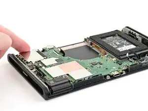
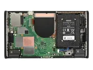
Place the board into the console at an angle so it sits underneath the metal grilles on the bottom edge of the console.
-
Use your fingers or a spudger to bend all the ribbon cables away from the board so they aren't stuck beneath it.
-
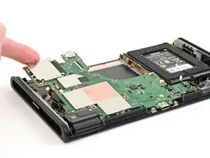
Lower the board into the console.
-
-
-
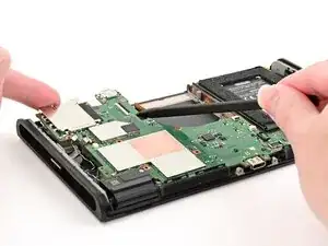
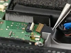
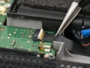
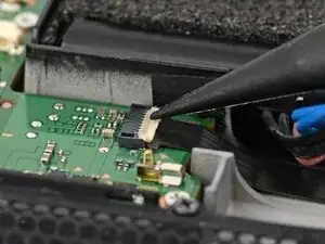
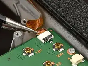
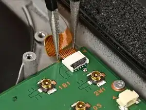
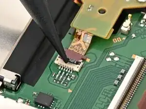
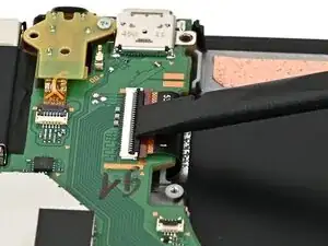
Use tweezers to insert the left Joy‑Con 2 connector cable into its ZIF connector on the board until it's fully seated.
-
Use your finger or a spudger to flip the hinged locking flap down to secure the cable.
-
-
-
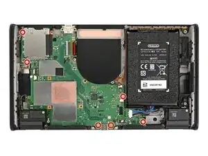
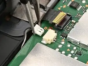
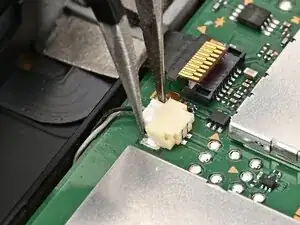
Align the left speaker cable's white JST connector with its socket on the board.
-
Use tweezers or your fingers to fully seat the connector into its socket.
-
-
-
Align the right speaker cable's JST connector with its socket on the board and push it in until it's fully seated.
-
-
-
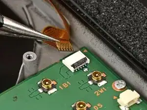
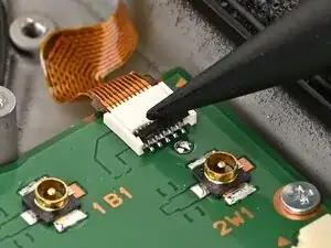
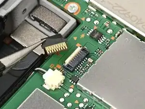
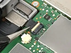
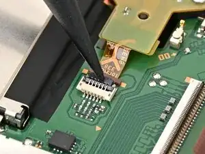
Use tweezers to insert the right Joy‑Con 2 connector cable into its ZIF connector on the board until it's fully seated.
-
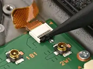
Flip the hinged locking flap down to secure the cable.
-
-
-
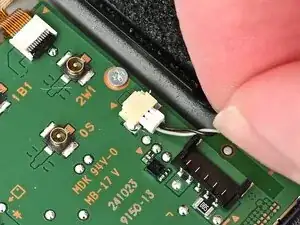
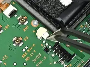
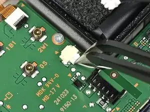
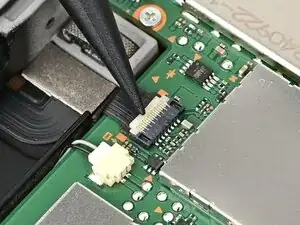
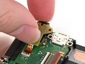
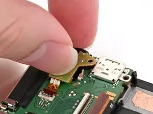
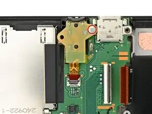
Insert the microphone cable into its ZIF connector, then set the microphone into its slot in the frame.
-
Flip the hinged locking flap down to secure the microphone cable.
-
-
-
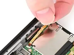
Guide the headphone jack cable into its connector, then set the assembly into its recess in the frame.
-
-
-
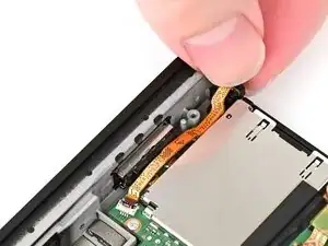
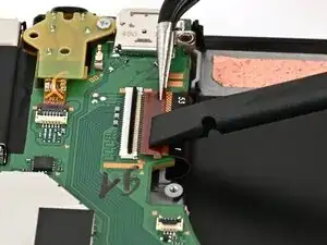
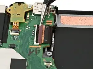
Use tweezers or your fingers to slide the screen cable into its ZIF connector until it's fully seated.
-
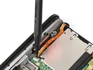
Flip the hinged locking flap down to secure the cable.
-


To reassemble your device, follow these instructions in reverse order.