Introdução
Ferramentas
-
-
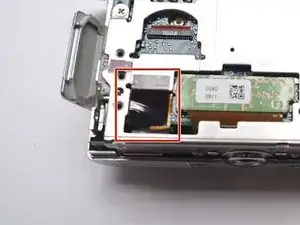
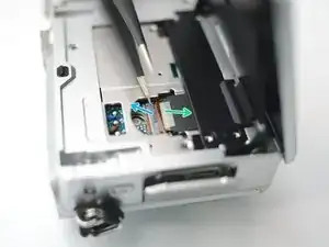
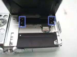
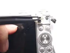
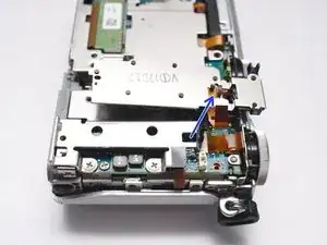
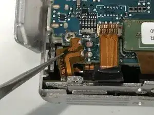
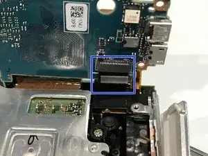
The FPC cable is inserted from right side of this photo.
-
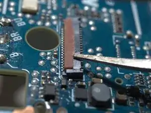
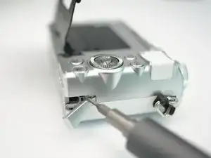
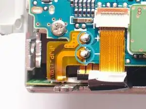
Insert a fine tip tweezer or any thin flat tip tool under the latch, and gentally lift it.
-
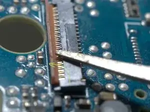
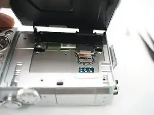
The latch rotates CCW for about 90 degrees
-
-
-
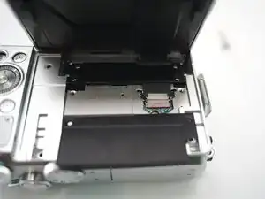
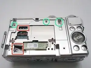
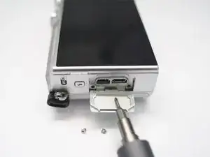
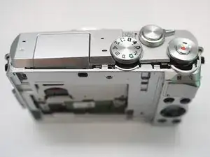
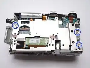
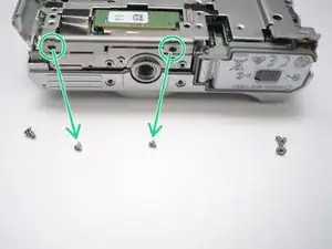
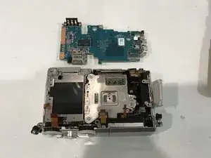
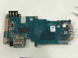
Left side, in connector bay, remove 2 screws.
-
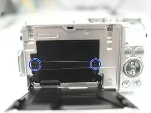
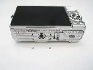
Bottom, reomve 2 screws
-
Right side, remove 1 screw
-
-
-
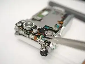
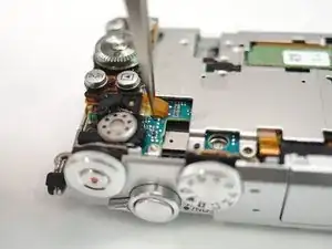
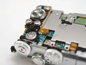
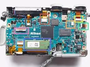
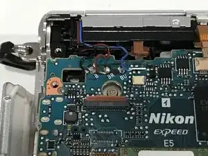
Flash solenoid and detect
-
Microphones and AF assistant LED
-
Keypad
-
Switches
-
NFC
-
WiFi and Bluetooth, Lens(back)
-
CMOS sensor
-
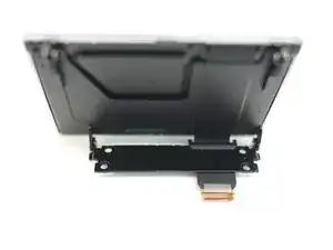
LCD
-
Conclusão
To reassemble your device, follow these instructions in reverse order.