Introdução

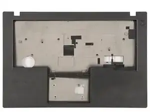
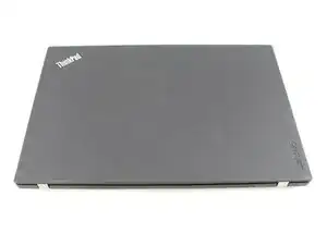
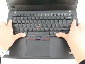
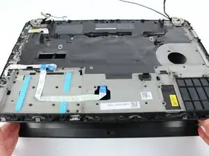
If you need to replace the palmrest of your ThinkPad T480, read this guide.

As someone who has used ifixit for many years, I feel like i should contribute.

I have done tons of work on my thinkpad, and looking at the t480 page, i realized nobody had done a guide on replacing this.

so here we are :3

  1. IsnhEpxDL1S62wJb
    IsnhEpxDL1S62wJb
    crrVCEAMWal4MQYJ
    • Disable the battery, power down, and unplug your device before you begin.

    • Flip the laptop over so the bottom of the device is showing.

    EN: NOTE: The built-in battery needs to be disabled first! This can be done in the BIOS.

    DE: ANMERKUNG: Die eingebaute Batterie muss zuerst deaktiviert werden! Dies kann im BIOS getan werden.

    Thomas -

  2. JImDPDOLndVQGGwS
    JImDPDOLndVQGGwS
    gp3rFiNWn4YLJqUR
    lkVNtucsw11AlWrR
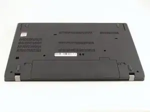
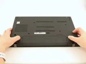
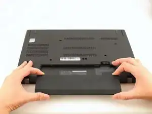
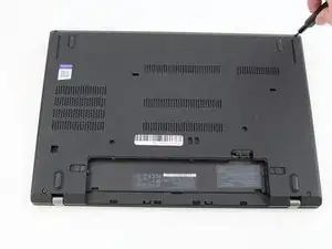
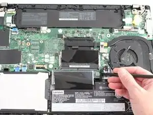
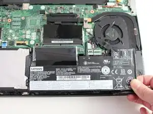
    • Using your fingers, slide the lock on each side of the battery to the unlocked position.

    • Remove the battery from the slot.

  3. lPHoAUKAAuccSMEE
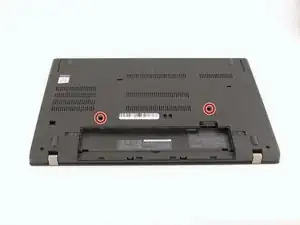
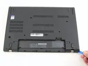
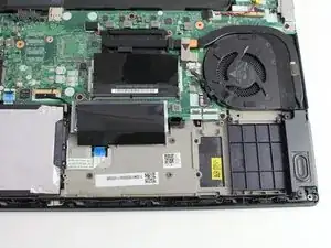
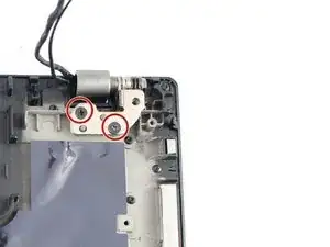
    • Use the Phillips #1 screwdriver to loosen the two screws parallel to the battery compartment.

  4. fCPrbeBfKqxnFEUX
    • Open the laptop so the keyboard is facing you.

  5. 1RdQIVLJDEvUpWaw
    1RdQIVLJDEvUpWaw
    6Fhj3MAtQWggIAQH
    OgvHWL2R4i6iRZU5
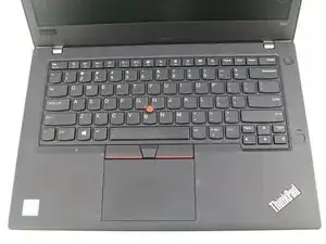
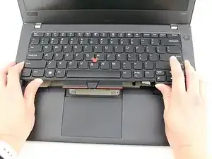
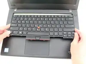
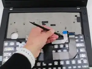
    • Push the keyboard towards the screen and away from the trackpad and then slide it out towards you gently.

    • The keyboard is connected to the board by two ribbon connectors.

    • Be careful not to rip the connectors when you flip the keyboard over.

  6. gGxeHC22ZHQIhWrb
    gGxeHC22ZHQIhWrb
    pVTYXgOc1POqftpD
    QxddCIY52aiGvfyB
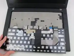
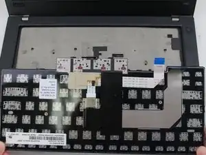
    • Flip the keyboard over towards you to expose the backside of the keyboard and the two ribbon connectors.

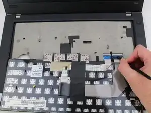
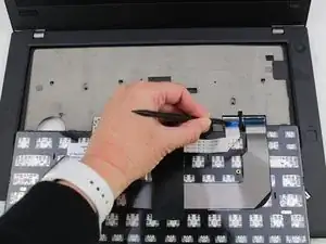
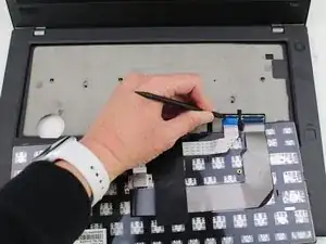
    • Using the black nylon spudger, flip the first ribbon connector lock open. Slide the first connector out.

  7. XHb2ZDiEddTaKN5d
    XHb2ZDiEddTaKN5d
    QRSbDwWAMvBBokWO
    NcowvotP1rNEtiR5
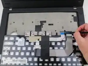
    • Using the black nylon spudger, unlock the second ribbon connector and slide it out from the port.

    Hello Sarah,

    Thanks for this great guide.

    I mistakenly broke this ribbon connector on my T480 and wish you will help with any info where to source a good one and how to fit it back. It has prevent my keyboard from working.

    Adeyinka Olugbade -

  8. 4CWbATUEMCJyvrGN
    4CWbATUEMCJyvrGN
    rOwirspDR1iYOpIx
    • Remove the keyboard from the laptop.

  9. E1PWOUdEVSVKIAN2
    E1PWOUdEVSVKIAN2
    R3yUwvFbSoSNAl2O
    • Using the Phillips #1 screwdriver, loosen the six captive screws.

  10. 4UMQtbC5yMPQDGDG
    4UMQtbC5yMPQDGDG
    nZwHZQAuROh1AUQm
    Ffv6mtRVNaYvSJFg
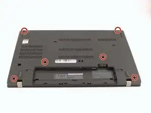
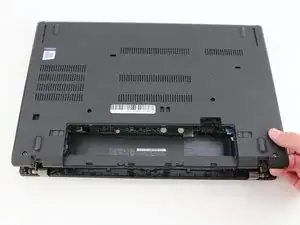
    • Insert the blue plastic opening tool into the space between the lower case and the chassis.

    • Slide the opening tool around the perimeter of the case to release the clips holding the case and the chassis together.

    • If it feels like the battery well portion of the back cover isn't loose, these clips may be holding the cover to the laptop. Use your opening tool to pry the clips loose and try removing the cover again.

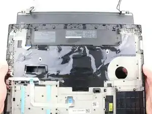
    • Remove the back case.

    I found a tough spudger (or even better a plectrum) is best here as the clips, although easy to separate, hold the case firmly leaving a tight gap which a soft spudger may fail to enter.

    Benjamin Kinsey -

    Hi Benjamin, thanks for the tip!

    Sarah Westberg -

    You also have to pry the near the battery. I experienced that you can't pry the front side.

    Minko Kelko -

    I used a credit card to pry the clips loose, it worked great. Added 2nd RAM stick easily.

    NFR Computers -

  11. Dp4ruFSV1XShvJHA
    Dp4ruFSV1XShvJHA
    DZgJRSuysLNTRUTA
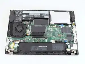
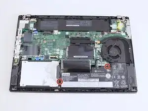
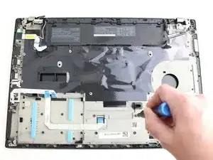
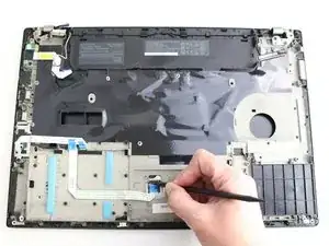
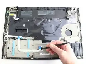
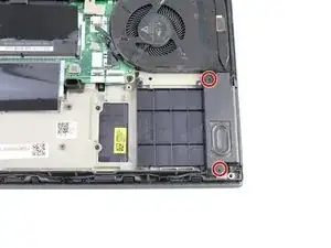
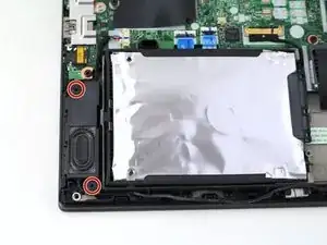
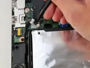
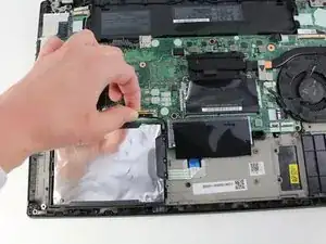
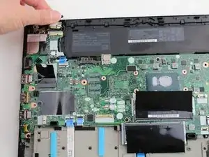
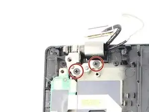
    • Use a Phillips #1 screwdriver to remove the two 4.6 mm screws that secure the internal battery to the frame.

  12. d2BHjhJZ5SS4YVHY
    d2BHjhJZ5SS4YVHY
    AhMMEoiFlEiIXit1
    eJ1fGJPJGabEuQ4l
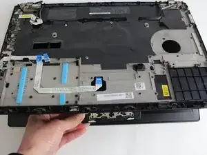
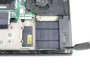
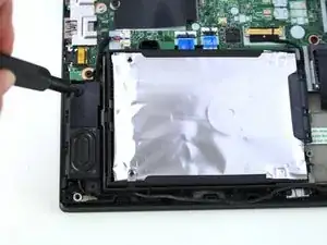
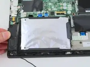
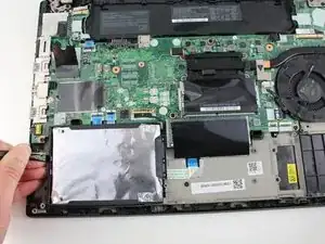
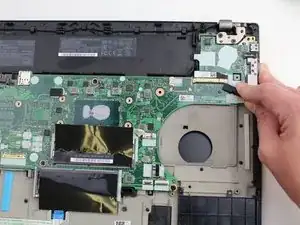
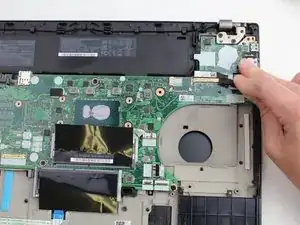
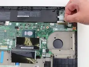
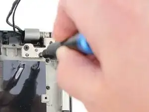
    • Use the spudger to slide the battery socket connector parallel to the motherboard and out of its socket on the motherboard.

  13. 3Buro4rTwTh6oRWC
    3Buro4rTwTh6oRWC
    jORCGqdFFBilhTkU
    • Lift the battery straight out of its recess and remove it.

    • If the battery is difficult to remove from the recess, use a nylon spudger to gently lift it on one edge, making it easier to grasp and remove by hand.

    • To prevent damage or potential fire, do not bend or flex the battery. Only use a plastic spudger and avoid any sharp tools that could puncture the battery.

    DO NOT wedge out the battery - T480 has two screws that hold down a plastic battery tray which easily lifts out after the two frame screws are removed. Wedging out will ruin the battery and could damage the cell and cause a fire.

    Poseidon219 -

    The guide says to remove those two screws. They are "lifting" with the wedge. Probably more of a way to promote their tools than out of necessity, but idk

    Lorenzo Serrano -

    You lift the internal battery first from the top, and then the bottom.

    This is because there are 2 "clips" on the bottom that the battery uses to slide into the chassis.

    Tai Lam -

  14. KJpyBZAgiD3nTQYh
    KJpyBZAgiD3nTQYh
    F1KeoQouHybrWBpC
    • Using the Phillips #1 screwdriver remove the four 3.1 mm screws from the chassis.

    • In this guide additional components have been removed. Your laptop internals will look slightly different than the images in Steps 8-10 because of this.

  15. o6PPDg6Q1pcHgBJW
    o6PPDg6Q1pcHgBJW
    frfteawPkaCDPUSQ
    J6ARleWeViBgRG5P
    • Using the black nylon spudger, remove the ribbon cable connected to the trackpad.

  16. g6XHBNbJUlbccHsa
    g6XHBNbJUlbccHsa
    KymxeFTBhckpvguG
    • Lift the chassis up and the trackpad will fall out.

    • When reinserting your trackpad, screw in the screws about halfway, and then center the trackpad. Then finish screwing them in. Otherwise, it may be off-center and might not click down.

  17. FMSUUYLUqMo1QEcE
    FMSUUYLUqMo1QEcE
    uZp3QEG56XvsWqsm
    • Using the Phillips #1 screwdriver, remove two 4.8 mm screws from the right speaker.

  18. 2VHUwx2eN4lZ5FHb
    2VHUwx2eN4lZ5FHb
    oiFFZwZNo5RBLZbR
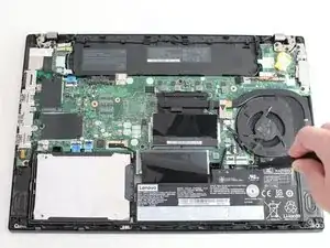
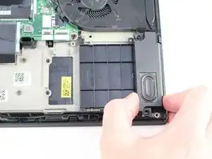
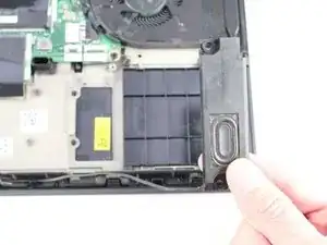
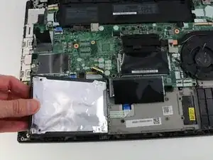
    • Lift the right speaker out of the case.

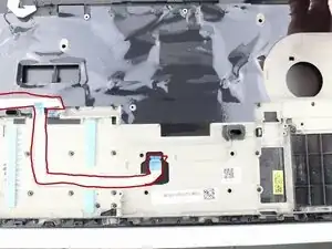
    • Gently remove the speaker cable from the perimeter of the chassis, connecting the right speaker to the left speaker.

  19. MVMOPWecCZhskiv2
    MVMOPWecCZhskiv2
    3QCXqQjb3AsF1Kf2
    • Remove two 4.8 mm screws from the left speaker using the Phillips #1 screwdriver.

  20. ZIQnUF3LQx6XRZCr
    ZIQnUF3LQx6XRZCr
    TMa221olRrXjSImD
    SbFmO4L3YLJPWisY
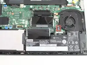
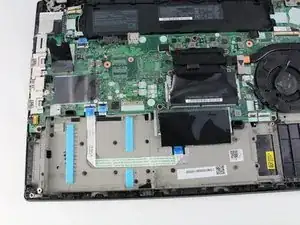
    • Using the black nylon spudger, remove the slide connector which attaches the left speaker to the motherboard.

    • Remove the left speaker from the case.

  21. TlwXClVqXGubyhAn
    TlwXClVqXGubyhAn
    emZqPGRJEZko3gZ2
    14hyDUTsPEdsFB2v
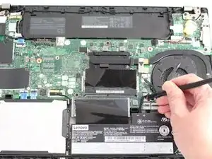
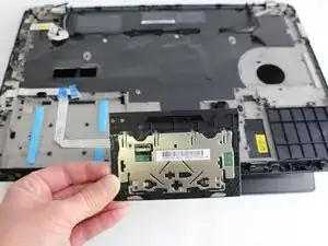
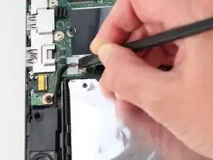
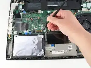
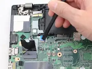
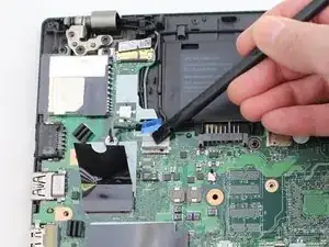
    • Using the black nylon spudger, lift the connector lock up.

    • Disconnect the storage cable from the system board.

  22. rPxmNT22GQZgWlEy
    rPxmNT22GQZgWlEy
    l1hfCLIJiJxtnopj
    3LYmB4lI21LU6koZ
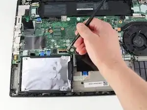
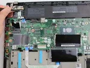
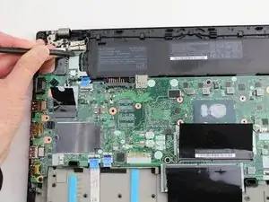
    • Lift the hard drive up with a tab if it has one or with your spudger.

    • Lift the drive assembly from the system.

  23. M6Zj64Eagu2NW5W1
    M6Zj64Eagu2NW5W1
    LcTxPieg5B2GJxKu
    • Using the Phillips #1 screwdriver, remove three 4.6 mm screws from the I/O bracket.

  24. ydGneydXr4HJkSOq
    ydGneydXr4HJkSOq
    IGhLeJG2fRfPZvnW
    • Lift the I/O bracket off the motherboard.

  25. SUrOHTqUGZNatsaP
    SUrOHTqUGZNatsaP
    rGPf4ivbN6JPDwKa
    XUgTZA2AeG43MoZe
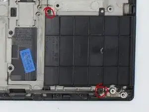
    • Using the Phillips #1 screwdriver, remove the three 4.1 mm screws from the RJ45 bracket.

    • Lift the bracket off of the motherboard.

  26. MwCUnpYLkRyMEMqU
    MwCUnpYLkRyMEMqU
    2MJQI24XplMBuT2H
    SlU2BnffYs2VDfRK
    • Use the black nylon spudger to lift up the small locking flap on the power button cable's ZIF connector.

    • Slide the power button cable out of the ZIF connector.

  27. XAG5Rd1OSjpQERMR
    XAG5Rd1OSjpQERMR
    32tDQw1HDJNQApV1
    QO4PMj5GRgIZqNim
    • Using the black nylon spudger, disconnect the LCD cable from the motherboard.

    You got camera and display cable mixed up. The small one is for camera and the long one (50 pin) for screen.

    Tim Rosulnik -

    Steps 3-8, 11, 13-16, 18-19, 21-29 can be skipped. Also, there is a step missing for unscrewing screen lid from body.

    Tim Rosulnik -

  28. CcgRUOQqU4WPVxMI
    CcgRUOQqU4WPVxMI
    MyBsFrKQ3vIvQHfT
    d3HIVeRTIYZ4HoYF
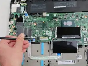
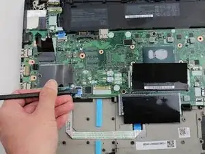
    • Use the tip of a spudger or an opening tool, to flip up the small, hinged locking flap on the camera cable connector to remove the cable from the motherboard.

  29. 2K34vgUmSPeGXUO6
    2K34vgUmSPeGXUO6
    GXPQUBmlSMKWTpTx
    ET4yUrm5NInTykCN
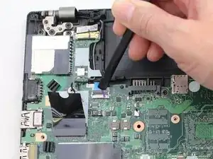
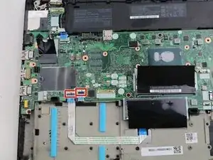
    • Using the black nylon spudger, remove the NFC cable connector and trackpad connector from the motherboard.

  30. yLYpnoF2u2hFcwq5
    yLYpnoF2u2hFcwq5
    HkbbftMU1ZDCUhoC
    G31tOBEYB4gIblYy
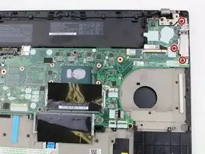
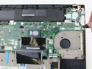
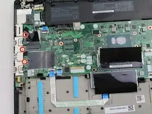
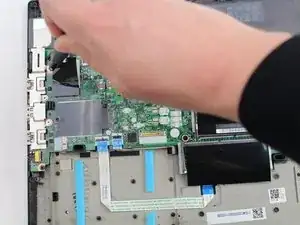
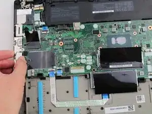
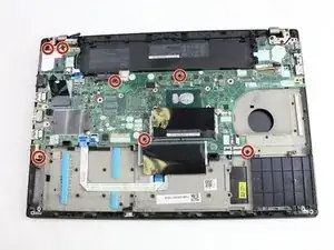
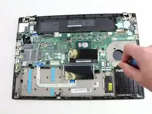
    • Using the Phillips #1 screwdriver, remove seven 3.6 mm screws from the motherboard.

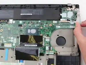
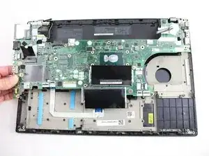
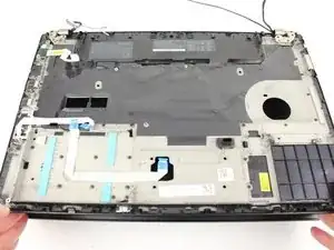
    • Lift the motherboard off of the case to remove it.

  31. Ax3RJYBwAKOUCrAu
    Ax3RJYBwAKOUCrAu
    AVOIcUp4VYJii3Au
    • Remove the cables from the cable guides.

  32. xOQSWpAphuePNPs4
    xOQSWpAphuePNPs4
    kgOysKVWvTX3GEXq
    poMujHspUWh3XOpk
    • Using the Phillips #1 screwdriver, remove two 4.3 mm screws from each hinge (four total).

    • In this image, all of the internal components were removed prior to this step so your device will look somewhat different.

    These screws were tricky for me. Be careful not to strip. I had success with a Phillips #2 and needed to apply a decent amount of vertical force into the screw before turning.

    Mark Schott -

  33. fxTPHXfJfQSH22TD
    fxTPHXfJfQSH22TD
    tPuHx3Qv1GqnZoUT
    PysbYGZjmMLSfXes
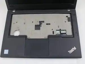
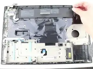
    • Lift the keyboard bezel up and slide it out from the hinges to separate it from the LCD assembly.

    • In this image, all of the internal components were removed prior to this step so your device will look somewhat different.

  34. KQ1TNfssv3OQuelK
    • Remove the trackpad ribbon from the old palm rest and move it to the same spot on the new one. Pull it up carefully and glue it down or use kapton tape.

    temporary image, I will replace this later

    Slash -

  35. DAVcx1sCp25itxwk
    • Unscrew the two screws in the smart card reader and remove it

Conclusão

To reassemble your device, follow these instructions in reverse order. If I missed anything, Please feel free to update my guide.

Things to remember during reassembly

Make sure to put everything back in the new palm rest, not the old one. (I made that mistake)

When reattaching the fan, please reapply thermal paste: follow this guide.

When putting the trackpad back in, make sure to center it before fully screwing it in.

Good luck, take your time, and don't break any connectors off of the motherboard.

Slash

Membro desde: 08/01/26

471 Reputação

0 comentários