Introdução
Use this guide to replace damaged or malfunctioning hinges in the Lenovo Flex 11 Chromebook za27 Model. The hinges provide 360-degree rotation, allowing the Chromebook to have four versatility modes—i.e., laptop, tent, stand, and tablet.
Signs Chromebook hinges need replacement are:
- Difficulty opening or closing device
- Misalignment
- Visible damage (i.e., cracks, rust, corrosion, etc.)
Before beginning this guide, make sure to power off the Chromebook and disconnect from any external power sources to prevent electrical harm.
Warning: Chromebook hinges are attached to fragile plastic mounts, which can break under stress. If the mount parts are broken, the back cover may need to be repaired using epoxy or replaced as a whole.
After following this replacement guide, ensure proper disposal of unused hinges as they are considered electronic waste, and contain a mix of metals/ plastics. To prevent environmental harm, Lenovo offers a variety of recycling programs and services to assist equipment users in recycling their IT products.
For more information about which programs are around your area, please visit:
Or you can search for certified local e-waste recyclers through resources by the EPA, Earth911, or e-stewards.
This guide requires basic technical skills, careful handling, but no specialized training needed.
Peças
-
-
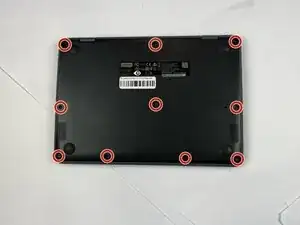
Close the lid and turn the laptop over so the underside is facing up.
-
Use a Phillips #00 screwdriver to remove the ten 7 mm-long screws on the lower case.
-
-
-
Flip the Chromebook over again.
-
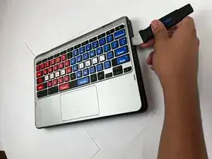
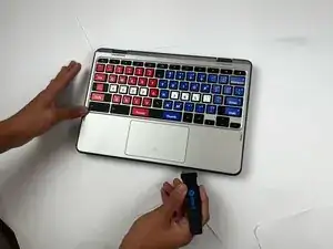
Open the lid 180 degrees, folding the Chromebook in half like a tablet.
-
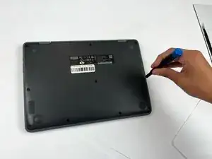
Insert an opening pick between the palmrest and keyboard assembly and the chassis.
-
Slide the pick around the perimeter until the assembly releases.
-
-
-
Slowly lift the palmrest and keyboard assembly, with care not to strain the connected ribbon cables.
-
Flip up the locking flap securing the keyboard ribbon cable.
-
Disconnect the keyboard ribbon cable.
-
-
-
Flip up the locking flap securing the touchpad ribbon cable.
-
Disconnect the touchpad ribbon cable.
-
Remove the palmrest and keyboard assembly.
-
-
-
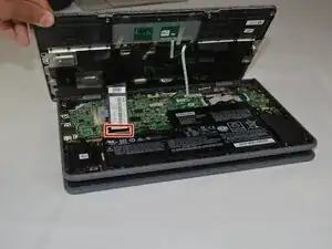
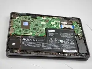
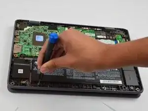
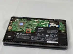
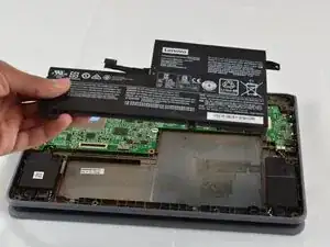
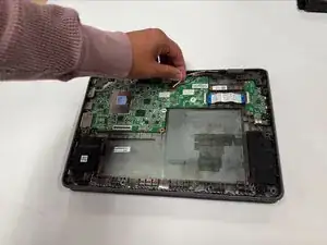
Use your fingernails to gently "walk" the battery connector directly out of its motherboard socket.
-
Remove the battery.
-
-
-
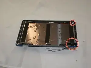
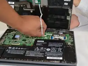
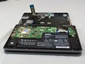
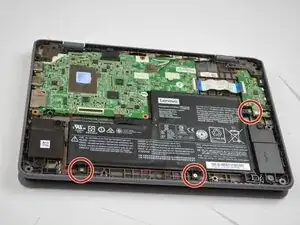
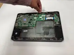
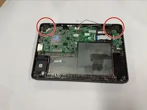
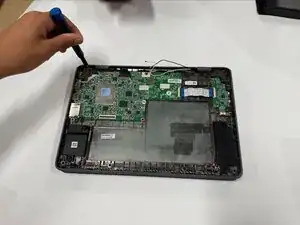
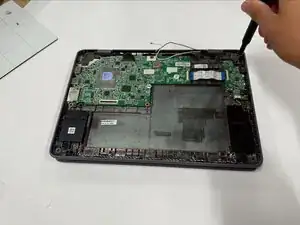
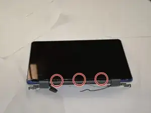
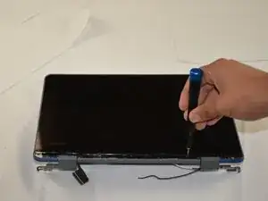
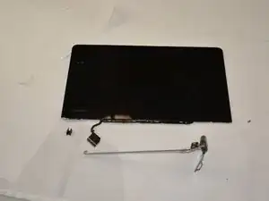
Remove the six 5.4 mm-long Phillips screws securing the two hinges.
-
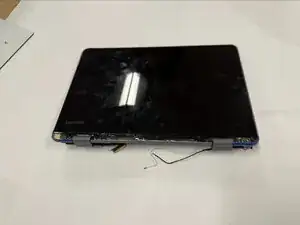
Remove the display assembly.
-
-
-
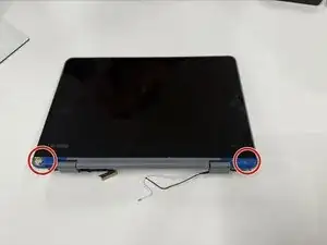
Using tweezers, remove the small rubber screw covers to reveal the screws underneath.
-
Unscrew the two 3.5 mm-long Phillips screws.
-
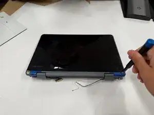
Remove the hinge cover.
-
-
-
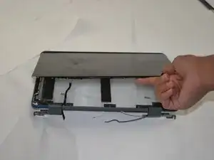
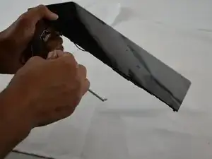
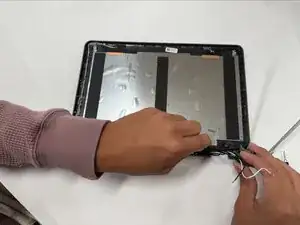
Using fingernail pressure or a plastic opening tool, pry the LCD bezel (screen) up from the LCD panel (case).
-
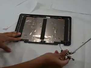
Slide the LCD bezel downwards to unhook it from the LCD panel.
-
Move the LCD bezel to the right of the LCD panel to expose the bracket underneath.
-
-
-
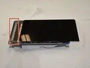
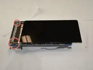
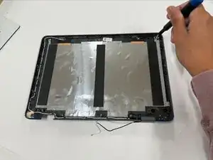
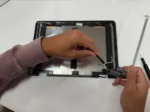
Remove the three 3.5 mm-long screws and one 2 mm-long bracket screw from the left side of the panel with a Phillips screwdriver.
-
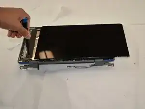
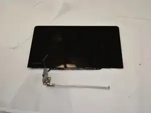
Remove the bracket and LCD bezel from the LCD panel.
-
-
-
Using tweezers, pry the small cover inside the remaining hinge out.
-
Gently remove the cable inside of the hinge.
-
-
-
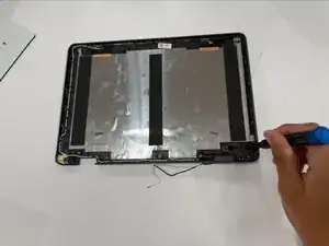
Remove the remaining three 3.5 mm-long screws and one 2 mm-long bracket screw from the right side of the LCD panel with a Phillips screwdriver.
-
-
-
Slide the bracket down the black and white cables attached to the LCD panel.
-
Using tweezers, pry the small cover inside the remaining hinge out and remove the black and white cables.
-

To reassemble your device, follow the above steps in reverse order.
Take your e-waste to an R2 or e-Stewards certified recycler.
Repair didn’t go as planned? Try some basic troubleshooting or ask our Answers community for help.