Introdução
-
-
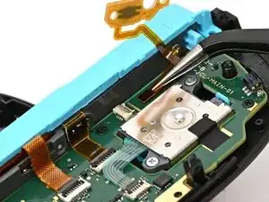
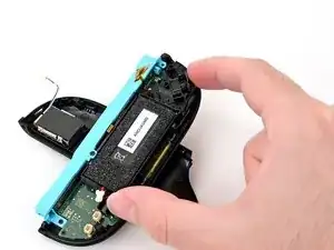
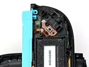
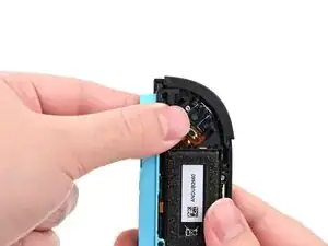
Make sure the locking flap is flipped up on the trigger cable's ZIF connector.
-
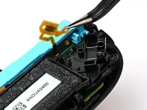
Position the trigger button board so its ribbon cable is aligned with its ZIF connector on the board.
-
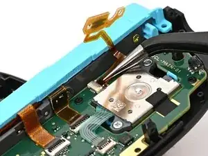
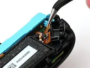
Use tweezers or your fingers to gently slide the ribbon cable into its ZIF connector.
-
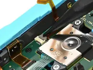
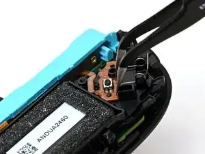
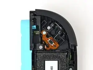
Flip the locking flap down to secure the cable.
-
-
-
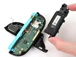
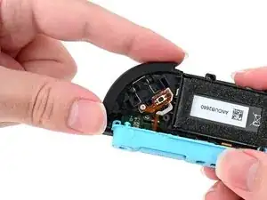
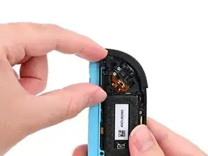
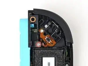
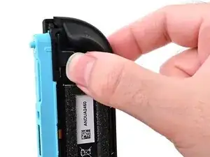
Use tweezers or your fingers to set the bottom edge of the trigger button board underneath the tab on the midframe.
-
Press the board into place so the black peg on the midframe protrudes through the hole on the bottom corner of the board.
-
-
-
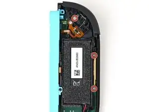
Use a JIS 00 driver to install the 3.9 mm‑long silver screw securing the trigger button board.
-
-
-
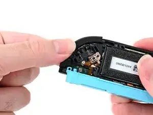
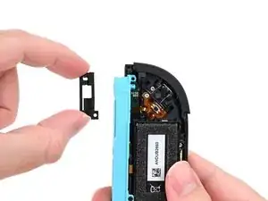
Align the release button bracket with its screw holes and set it in the frame so it snaps into place.
-
-
-
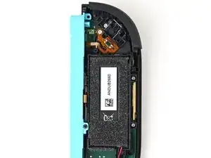
Use a JIS 00 driver to install the two screws securing the release button bracket:
-
One 3.9 mm‑long silver screw
-
One 6.2 mm‑long black screw
-
-
-
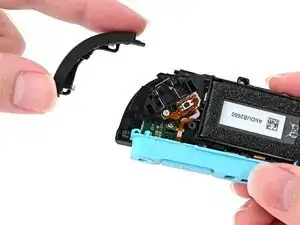
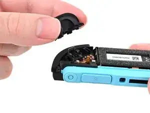
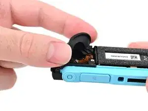
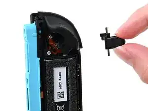
Align the trigger button with the top of the controller, with the ZL engraving facing out.
-
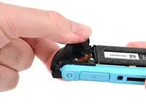
Set the trigger button onto its metal spring. Ensure the legs of the metal spring are seated properly in their channels on the midframe.
-
Press firmly on the trigger button to snap it into place.
-

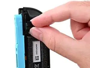
To reassemble your device, follow these instructions in reverse order.

It might not be obvious, but the ribbon goes in with the copper facing down. That's why the images above show the solid-color other side of the ribbon. This makes the "flat" ribbon, with no twists, travel outside the board. If you put the ribbon in the wrong way, the ZL button will not work. Everything else about the instructions is correct!
MrCab -