Introdução
Use this guide to trace and correct the most common causes of heat loss in your stackable Electrolux front-load dryer. You will verify incoming power, open the cabinet, test every heat-related component, replace any failed parts, and confirm that the machine heats again. Follow each safety notice and keep photographs of every harness so re-assembly is trouble-free.
-
-
Collect a Phillips head screwdriver for all cabinet screws.
-
Keep a digital multimeter ready for voltage and resistance checks.
-
Add a vacuum with a flexible hose to clear lint from the vent path.
-
-
-
Remove the single rear screw and lift off the small metal cover over the terminal block.
-
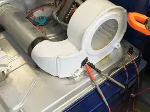
Set the meter to AC volts and read between center neutral and left hot; expect about 120 V.
-
Move the probe to the right hot and confirm another 120 V.
-
Measure across the two outer hots and verify 208–240 V AC.
-
-
-
Back out the two Phillips screws at the rear corners of the top panel.
-
Slide the panel rearward and lift it off the cabinet.
-
-
-
Undo the two screws that anchor the user interface to the front bulkhead.
-
Disconnect the multipin harness, photographing its position for re-assembly.
-
Set the interface aside where it cannot fall or snag wires.
-
-
-
Open the door and remove the two screws recessed in the lint filter housing.
-
Close the door and remove the two bottom screws near each lower corner.
-
Take out the two top screws securing the panel to the chassis while supporting the door.
-
Tilt the panel forward, unplug the door-switch harness, and lift the panel up off its locating tabs.
-
-
-
Remove the two lower screws that fasten the bulkhead to the side panels.
-
Squeeze the cable-tie clip and release the door-switch harness from the bulkhead.
-
Lift the bulkhead up off its side tabs and pull it clear of the cabinet.
-
-
-
Reach inside on the right and pull the idler pulley to the left to slacken the belt.
-
Slip the belt off the motor pulley.
-
Use the belt as a sling to lift and slide the drum straight out of the front opening.
-
-
-
Vacuum the lint filter housing and vent duct until airflow is unobstructed.
-
If the duct is badly packed, reach in and pull out the lint wad by hand.
-
-
-
Pull the two wires off the black thermistor on the blower housing.
-
Set the meter to the 20–200 kΩ range and probe the terminals.
-
A room-temperature reading of 50–55 kΩ indicates a good sensor.
-
Any value far outside that window or OL means the thermistor is defective.
-
-
-
Disconnect the fuse leads on the exhaust duct.
-
Measure resistance; a good fuse reads roughly 0 Ω.
-
OL or infinite resistance indicates an open fuse that needs replacement.
-
-
-
Unplug the two wires from the rear thermostat on the heating canister.
-
Check continuity; near-zero ohms confirms the thermostat is functional.
-
Replace the thermostat if the meter shows OL or very high resistance.
-
-
-
Remove the wires from the middle-mounted thermal fuse.
-
A good fuse reads close to 0 Ω; OL means it is blown and must be replaced.
-
-
-
Detach all element wires, noting positions on 3 + 1 or 2-wire models.
-
Measure between the right motor post and each left post; 25–30 Ω is normal for 3 + 1 elements.
-
Measure between any two left posts; about 50 Ω is expected.
-
On 2-wire elements expect roughly 10 Ω across the pair.
-
-
-
Label and disconnect all wires from the canister and its sensors.
-
Remove the two front screws securing the canister feet to the base.
-
Use a stubby driver to remove the hidden screw at the back-right bulkhead tab.
-
Lift the canister forward and out of the dryer cabinet.
-
-
-
Unscrew the thermal fuse and thermostat from the old shell and install new or reused parts on the replacement.
-
Remove the two inner faceplate screws and separate the cover to access the element.
-
Seat the replacement element so its legs fit the recesses, then reinstall the foot screws.
-
Straighten any bent cover lip so it sits flush with the shell.
-
-
-
Slide the canister rear flange into the bulkhead opening and lower the feet into their base slots.
-
Secure the feet and reinstall the rear retaining screw if accessible.
-
Reconnect each wire to its original terminal, matching your photos.
-
-
-
Rest the rear rim of the drum on the two rear support rollers.
-
Loop the belt around the drum groove with the ribbed side inward.
-
Pull the idler to the left and guide the belt around the motor pulley and idler groove.
-
Rotate the drum by hand; smooth turning confirms proper belt routing and blower engagement.
-
-
-
Hang the bulkhead on its top tabs, seat it, and install the two bottom screws.
-
Clip the door-switch harness back into the bulkhead and plug it into the control board.
-
Reconnect the door-switch plug to the front panel, lower the panel onto its locating tabs, and install the two top screws.
-
Drive the two bottom panel screws and the two large filter-housing screws accessed through the open door.
-
-
-
Plug the interface harness into its original socket on the board.
-
Engage the interface tabs and fasten its two mounting screws.
-
Slide the top panel forward and secure it with the two rear screws.
-
-
-
Unplug the dryer, remove the crossbar screws, and lift the board out of its cradle.
-
Unlatch the plastic tabs and separate the PCB from the housing.
-
Examine both sides for burnt relays, dark traces, or cracked solder joints.
-
-
-
Reconnect all harnesses to the loose board but leave it unsecured for probe access.
-
Locate pins J52 J71 and J73 on the board using the tech sheet.
-
With the dryer running, measure between the black L1 wire at the terminal block and each pin; 208–240 V confirms a good relay.
-
A reading under 200 V indicates a failed relay and the board must be replaced.
-
-
-
Unplug the dryer, mount the control board, and reinstall its crossbar screws.
-
Verify every harness and screw is secure, restore power, and run a timed-dry cycle.
-
Confirm the drum tumbles, heat is present, and airflow is strong through the exhaust.
-
Your dryer should now heat reliably. Keep the vent path clear, clean the lint filter after every load, and replace fuses or thermostats in pairs if the machine ever overheats again. Store the tech sheet inside the cabinet for future diagnostics.