Introdução
Use this guide to replace the thermal pad in your Framework Laptop 16 Graphics Module.
This guide is applicable for both the NVIDIA® GeForce RTX™ 5070 and AMD Radeon™ RX 7700S Graphics Modules. There are slight visual differences between the two, but the procedure is identical.
After installation, the thermal pad needs to go through a few thermal cycles before it gets to full performance.
-
-
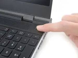
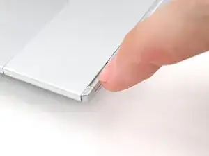
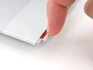
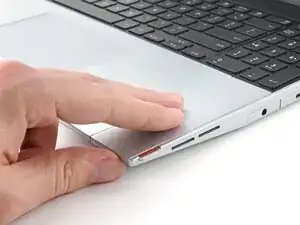
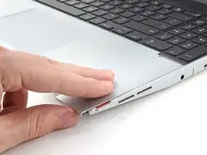
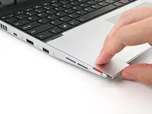
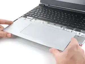
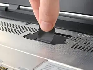
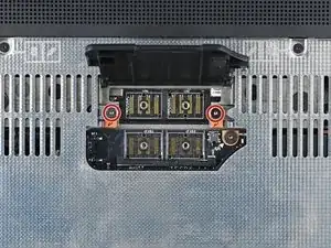
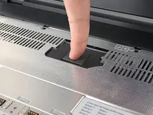
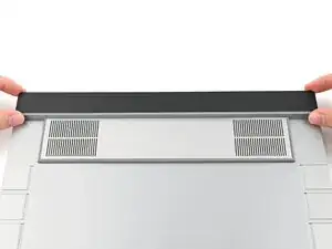
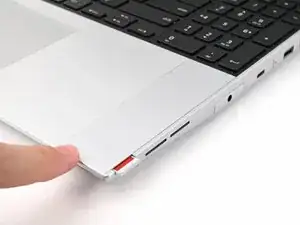
Use your fingers to slide the Touchpad Spacer toward the bottom edge of the laptop and unclip it.
-
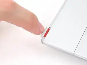
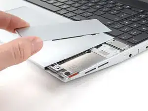
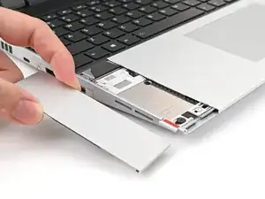
Lift the Touchpad Spacer off the laptop and remove it.
-
-
-
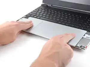
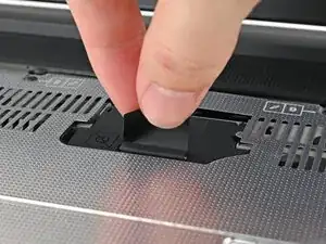
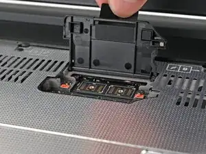
Use your fingers to slide the Touchpad Module toward the bottom edge of the laptop and disconnect it.
-
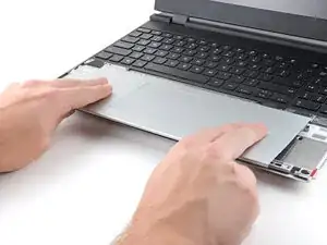
Lift the Touchpad Module and remove it.
-
-
-
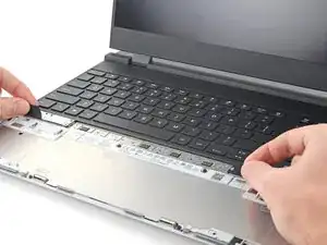
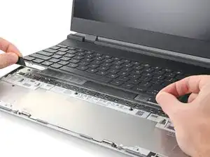
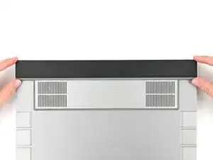
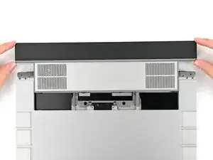
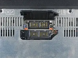
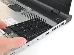
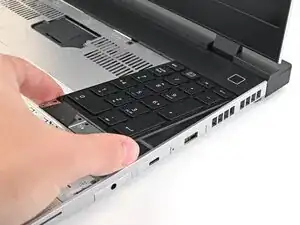
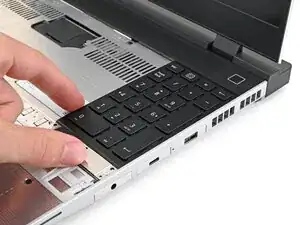
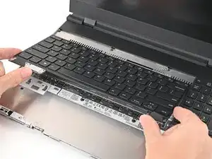
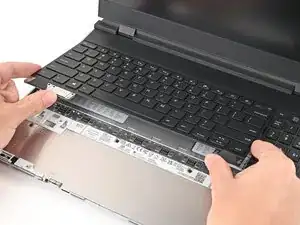
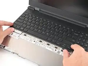
Grip the two pull tabs along the bottom of the keyboard and lift until its magnets release.
-
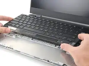
Remove the keyboard.
-
-
-
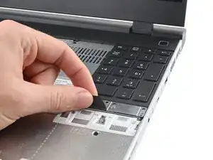
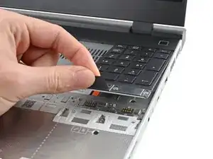
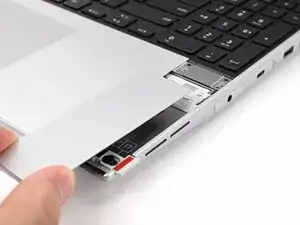
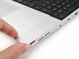
Grip the pull tab at the bottom of the Input Module and lift until its magnets release.
-
Remove the Input Module.
-
Repeat for any remaining Input Modules.
-
-
-
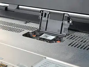
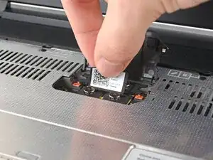
Use your Framework Screwdriver to loosen the four captive T5 Torx screws securing the interposer.
-
-
-
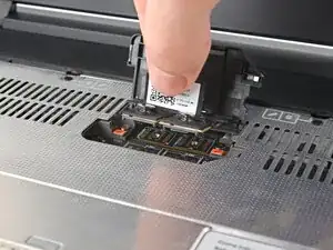
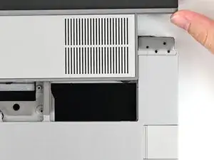
Use your Framework Screwdriver to loosen the two captive T5 Torx screws securing the Graphics Module.
-
Close the interposer door before continuing.
-
-
-
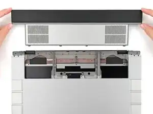
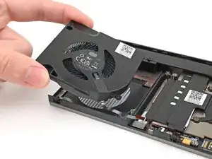
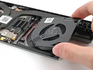
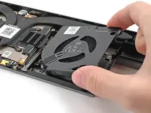
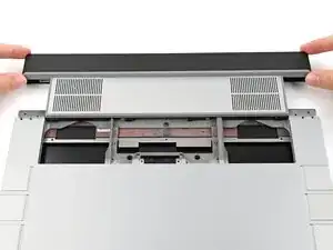
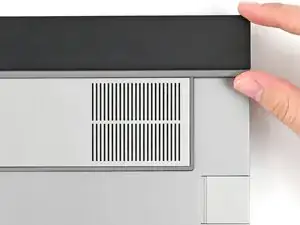
Close your laptop and flip it over.
-
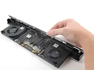
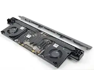
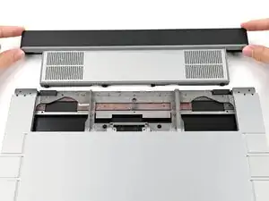
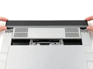
Slide the Graphics Module out of the laptop and remove it.
-
-
-
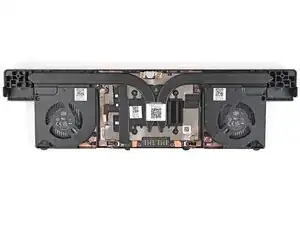
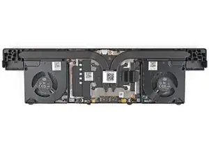
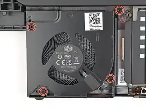
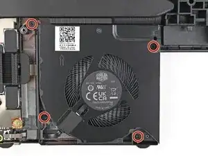
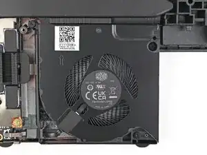
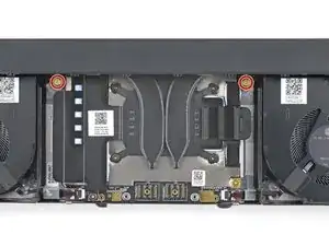
Use your Framework Screwdriver to remove the four 3.6 mm‑long T5 Torx screws securing the Graphics Module cover:
-
Two screws on the flat surface of the module, next to the fans.
-
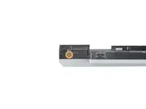
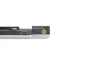
Two screws on the thin edge of the module, near the ends. You'll need to flip the module on its back edge to access them.
-
-
-
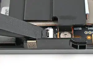
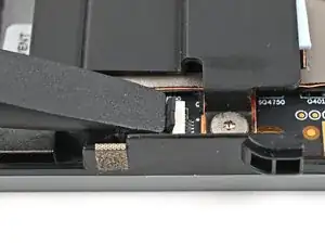
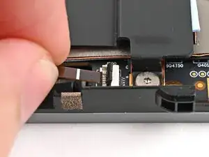
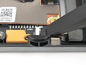
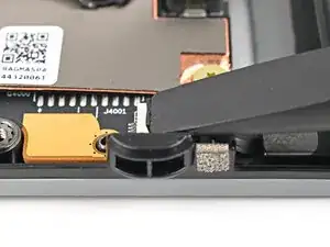
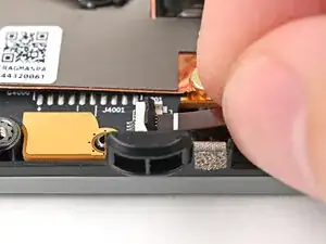
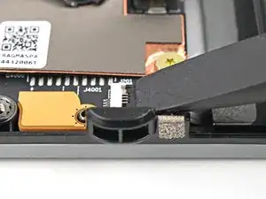
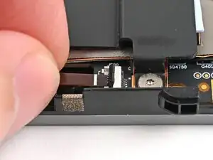
Use the flat end of a spudger, or a clean fingernail, to lift up and release the locking tab on the left fan ZIF connector.
-
Use your fingers to grip the brown pull tab and slide the fan cable straight out of its socket.
-
-
-
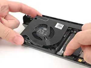
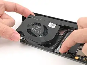
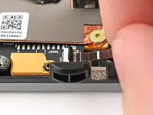
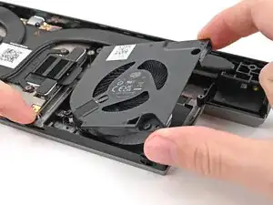
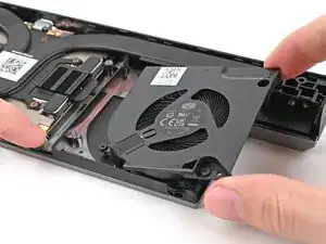
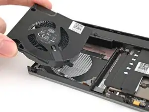
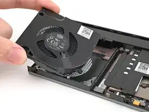
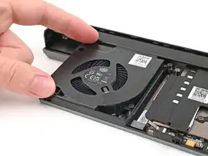
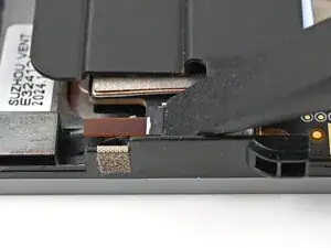
Use one hand to press the fan cable flat to the module.
-
Use your other hand to pull the fan out of its housing, making sure to thread the cable though its slot.
-
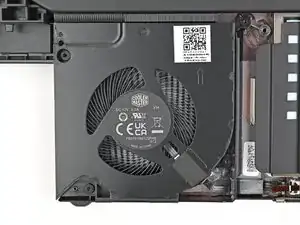
Remove the fan.
-
-
-
Use the flat end of a spudger, or a clean fingernail, to lift up and release the locking tab on the right fan ZIF connector.
-
Use your fingers to grip the brown pull tab and slide the fan cable straight out of its socket.
-
-
-
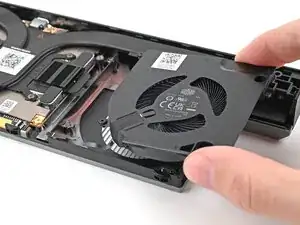
Use one hand to press the fan cable flat to the module.
-
Use your other hand to pull the fan out of its housing, making sure to thread the cable though its slot.
-
Remove the fan.
-
-
-
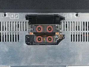
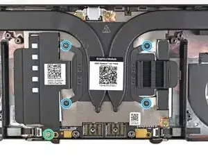
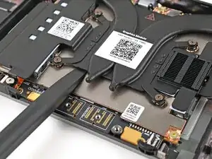
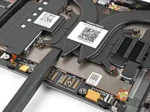
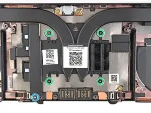
Use your Framework Screwdriver to loosen the captive T5 Torx screws securing the Graphics Module Heatsink:
-
Loosen the captive screw at the bottom left corner of the heatsink.
-
Loosen the captive screws directly over the GPU in order from 1–4 (the numbers are engraved on the metal near the screw).
-
-
-
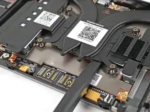
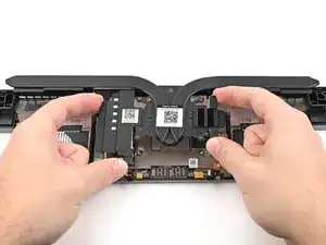
Use the flat end of the Framework Screwdriver to pry up the flat metal plate under the heat pipes until you feel the thermal pads separate.
-
-
-
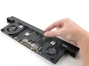
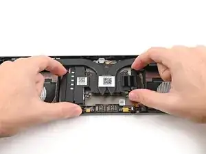
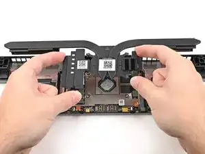
Grip the edges of the heatsink, near its curved pipes, and lift it straight up to remove it.
-
-
-
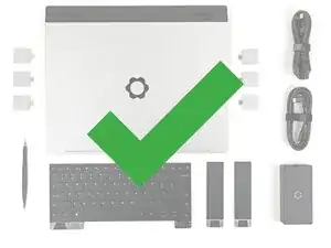
Congratulations on completing disassembly! The remaining steps will show how to reassemble your Framework Laptop.
-
-
-
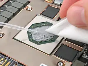
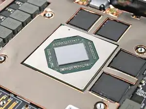
Use a few drops of high concentration (>90%) isopropyl alcohol and a lint-free cloth to wipe away the thermal compound residue.
-
-
-
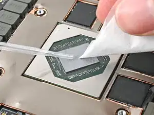
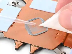
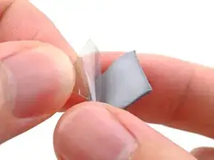
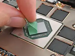
Peel off the clear liner from the thermal pad to expose one side of it.
-
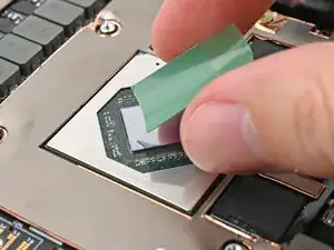
Place the exposed side of the thermal pad over the CPU.
-
-
-
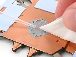
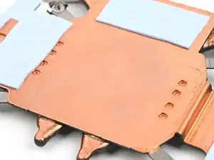
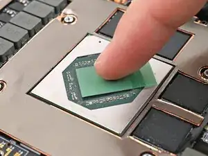
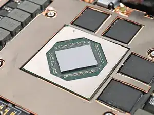
Use your finger to lightly press the thermal pad to the GPU and bond it.
-
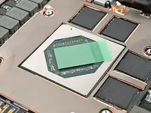
Remove the green liner from the thermal pad to expose its top side.
-
-
-
Use your Framework Screwdriver to tighten the captive T5 Torx screws securing the Graphics Module Heatsink:
-
Tighten the captive screws directly over the GPU in order from 4–1.
-
Tighten the captive screw at the bottom left corner of the heatsink.
-
-
-
Use your fingers to grip the brown pull tab and slide the right fan cable straight into its socket.
-
Use the flat end of your Framework Screwdriver, or a clean fingernail, to press down the locking tab on the fan ZIF connector.
-
-
-
Place the left fan onto the Expansion Bay Shell, making sure to thread the cable through its slot.
-
-
-
Use your fingers to grip the brown pull tab and slide the left fan cable straight into its socket.
-
Use the flat end of your Framework Screwdriver, or a clean fingernail, to press down the locking tab on the fan ZIF connector.
-
-
-
Use your Framework Screwdriver to install the four 3.6 mm‑long T5 Torx screws securing the Graphics Module cover:
-
Two screws on the flat surface of the module, next to the fans.
-
Two screws on the thin edge of the module, near the ends. You'll need to flip the module on its back edge to access them.
-
-
-
Flip over the laptop and open it.
-
Lift the interposer door by its black pull tab and let it rest upright.
-
-
-
Use your Framework Screwdriver to tighten the two captive T5 Torx screws securing the Graphics Module.
-
-
-
Use your Framework Screwdriver to tighten the four captive T5 Torx screws securing the interposer.
-
Close the interposer door.
-
-
-
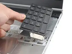
Grip the pull tab at the bottom of the numpad.
-
Lift the pull tab until the numpad magnets release.
-
Remove the numpad.
-
-
-
Align the top edge of the keyboard with the top edge of the laptop.
-
Lay the keyboard on the laptop and let the magnets pull the keyboard into place
-
-
-
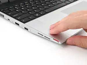
Place the Touchpad Spacer over its spot on the laptop with the bottom edge overhanging slightly.
-
Slide the Touchpad Spacer towards the top of the laptop to secure it.
-
Repeat the same procedure for the other Touchpad Spacer.
-


You finished fixing your Framework Laptop!
Take your e-waste to an R2 or e-Stewards certified recycler.
If you need help, contact Framework support.